Supercharge Your Innovation With Domain-Expert AI Agents!

Fingerprint-sensing apparatus

a fingerprint and sensor technology, applied in the field of fingerprint sensing apparatus, can solve the problems of reducing the recognition effect of the fingerprint ridge or the fingerprint valley, and achieve the effect of reducing the sensing time of the entire fingerprin

Active Publication Date: 2020-03-17
AU OPTRONICS CORP
View PDF14 Cites 0 Cited by
  • Summary
  • Abstract
  • Description
  • Claims
  • Application Information

AI Technical Summary

Benefits of technology

[0006]The invention provides a fingerprint-sensing apparatus. The fingerprint-sensing apparatus of the invention does not require a heating device and a heating circuit, and can effectively reduce the sensing time of an entire fingerprint.
[0008]Based on the above, the fingerprint-sensing apparatus of the invention includes a fingerprint-sensing pixel array and a plurality of read-out circuits. The fingerprint-sensing pixel array has a plurality of fingerprint-sensing pixel columns. The read-out circuits receive the thermosensitive current provided by the thermosensitive current generation circuit and generate a fingerprint-sensing signal according to the thermosensitive current. Therefore, the fingerprint-sensing apparatus does not require a heating device and a heating circuit. Moreover, the scanning switches of the plurality of fingerprint-sensing pixels in the same row of the fingerprint-sensing pixel array are controlled by the same row scanning signal, and therefore the fingerprint-sensing apparatus of the invention can effectively reduce the sensing time of an entire fingerprint.

Problems solved by technology

Moreover, when the thermal fingerprint-sensing apparatus is sensing a fingerprint, if the sensing time is too long, then the thermal fingerprint-sensing apparatus reaches thermal equilibrium, and as a result, the thermal fingerprint-sensing apparatus reduces the recognition effect of the fingerprint ridge or fingerprint valley.

Method used


Image

  • Fingerprint-sensing apparatus
  • Fingerprint-sensing apparatus
  • Fingerprint-sensing apparatus

Examples


Embodiment Construction

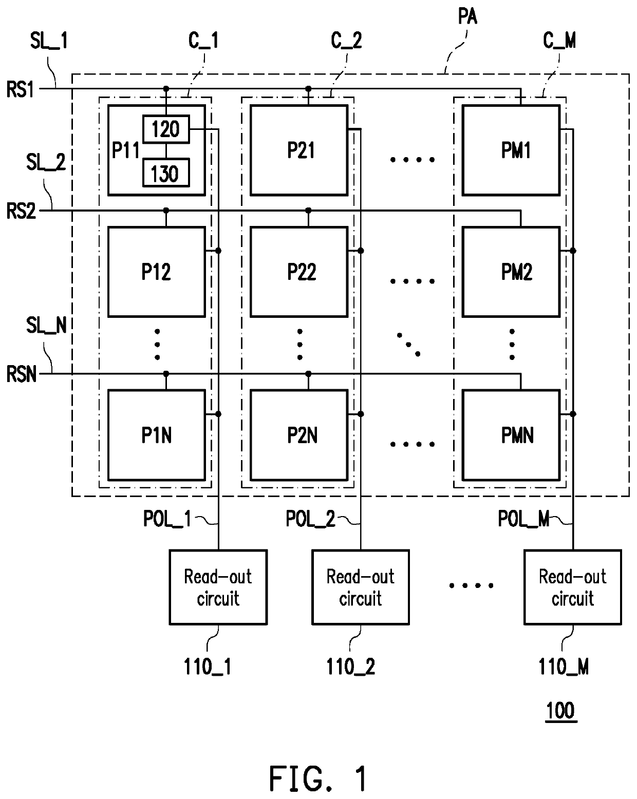
[0015]Referring to FIG. 1, FIG. 1 is a schematic of a fingerprint-sensing apparatus shown according to an embodiment of the invention. In the embodiment of FIG. 1, a fingerprint-sensing apparatus 100 includes a fingerprint-sensing pixel array PA and read-out circuits 110_1 to 110_M. The fingerprint-sensing pixel array PA has fingerprint-sensing pixel columns C_1 to C_M. The fingerprint-sensing pixel column C_1 includes fingerprint-sensing pixels P11 to P1N, and the fingerprint-sensing pixel column C_2 includes fingerprint-sensing pixels P21 to P2N . . . etc. In the present embodiment, fingerprint-sensing pixels P11 to PM1 in the same row in the fingerprint-sensing pixel array PA receive a row scanning signal RS1 via a row scanning line SL_1, and fingerprint-sensing pixels P12 to PM2 in the same row in the fingerprint-sensing pixel array PA receive a row scanning signal RS2 via a row scanning line SL_2 . . . etc. The read-out circuit 110_1 is coupled to the fingerprint-sensing pixel ...


PUM


Abstract

A fingerprint-sensing apparatus is provided. The fingerprint-sensing apparatus includes a fingerprint-sensing pixel array and a plurality of read-out circuits. The fingerprint-sensing pixel array has a plurality of fingerprint-sensing pixel columns, and each of the plurality of fingerprint sensing pixel columns includes a plurality of fingerprint-sensing pixels. Each of the plurality of fingerprint-sensing pixels includes a scanning switch and a thermosensitive current generation circuit. The scanning switch is controlled by a row scanning signal. The thermosensitive current generation circuit generates a thermosensitive current according to the fingerprint-sensing pixel corresponding to a fingerprint ridge or a fingerprint valley. The plurality of read-out circuits is respectively coupled to the plurality of fingerprint-sensing pixel columns. The read-out circuits receive the thermosensitive current provided by the fingerprint-sensing pixels and generate a fingerprint-sensing signal according to the thermosensitive current.

Description

CROSS-REFERENCE TO RELATED APPLICATION[0001]This application claims the priority benefit of Taiwan application serial no. 107109137, filed on Mar. 16, 2018. The entirety of the above-mentioned patent application is hereby incorporated by reference herein and made a part of this specification.BACKGROUND OF THE INVENTIONField of the Invention[0002]The invention relates to a sensing apparatus, and more particularly, to a fingerprint-sensing apparatus suitable for fingerprint recognition.Description of Related Art[0003]A thermal fingerprint-sensing apparatus has advantages such as resistance to pollution and interference caused by an electromagnetic signal and lack of an external optical system compared to an optical fingerprint-sensing apparatus and a capacitive fingerprint-sensing apparatus. Therefore, the thermal fingerprint-sensing apparatus has gradually gained attention.[0004]In general, the thermal fingerprint-sensing apparatus requires a plurality of heatable devices such that a...

Claims


Application Information

Patent Timeline
Patent Type & Authority Patents(United States)
IPC IPC(8): G06K9/00G06V10/143G06V10/147
CPCG06K9/0002G06K9/0008G06K9/001G06V40/1306G06V10/143G06V10/147G06V40/1359G06V40/1376
Inventor LU, WEN-JELIU, YU-JUNG
Owner AU OPTRONICS CORP
Features
  • R&D
  • Intellectual Property
  • Life Sciences
  • Materials
  • Tech Scout
  • Unparalleled Data Quality
  • Higher Quality Content
  • 60% Fewer Hallucinations
Learn More