
Display device and backlight driving method thereof

a backlight driving and display device technology, applied in static indicating devices, cathode-ray tube indicators, instruments, etc., can solve the problems of limited design of displayers and reduced use safety, and achieve the effects of preventing display devices from overheating, maximizing brightness, and improving image quality

Active Publication Date: 2020-03-17
WISTRON CORP
View PDF18 Cites 0 Cited by
  • Summary
  • Abstract
  • Description
  • Claims
  • Application Information

AI Technical Summary

Benefits of technology

[0004]Thus, the present disclosure provides a display device in which a backlight module can determine a driving current for the backlight module according to the received input image data thereby maximizing the brightness, so as to improve the image quality and prevent the display device from overheating.

Problems solved by technology

However, driving a backlight module with a large driving current may cause a thermal problem (for example, overheating), resulting in a limited designs for the displayer, reduced safety for use, and the like.

Method used


Image

  • Display device and backlight driving method thereof
  • Display device and backlight driving method thereof
  • Display device and backlight driving method thereof

Examples


Embodiment Construction

[0012]The following description is of the best-contemplated mode of carrying out the invention. This description is made for the purpose of illustrating the general principles of the invention and should not be taken in a limiting sense. The scope of the disclosure is best determined by reference to the appended claims.

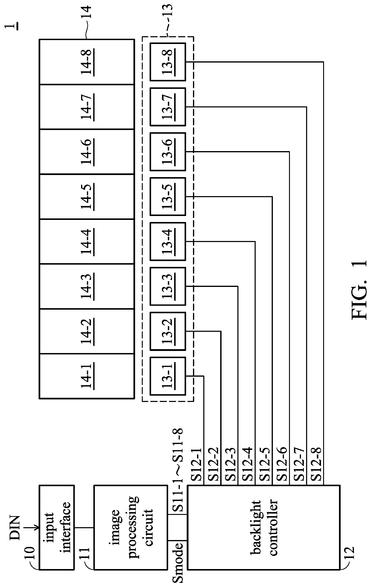
[0013]FIG. 1 shows an exemplary embodiment of a display device. Referring to FIG. 1, the display device 1 includes an input interface 10, an image processing circuit 11, a backlight controller 12, a backlight module 13, and a display panel 14. The display device 1 receives input image data DIN through the input interface 10. The input interface 10 may be a video graphics array (VGA), a digital video interface (DVI), or a high definition multimedia interface (HDMI). The backlight module 13 is controlled by the backlight control circuit 12 to emit light to the display panel 14. In the embodiment, the backlight module 13 includes a plurality of light source units. In the...


PUM


Abstract

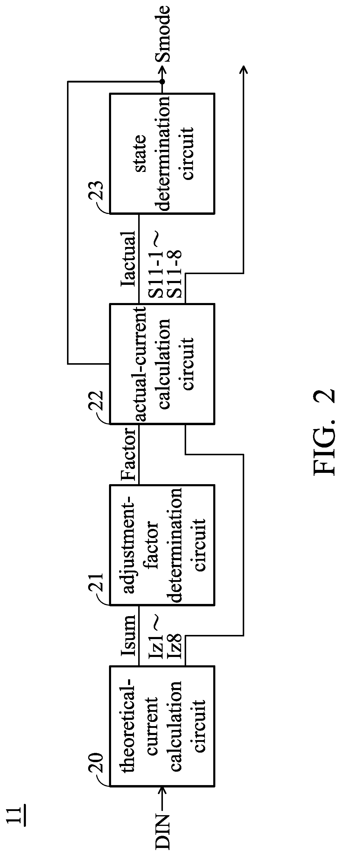
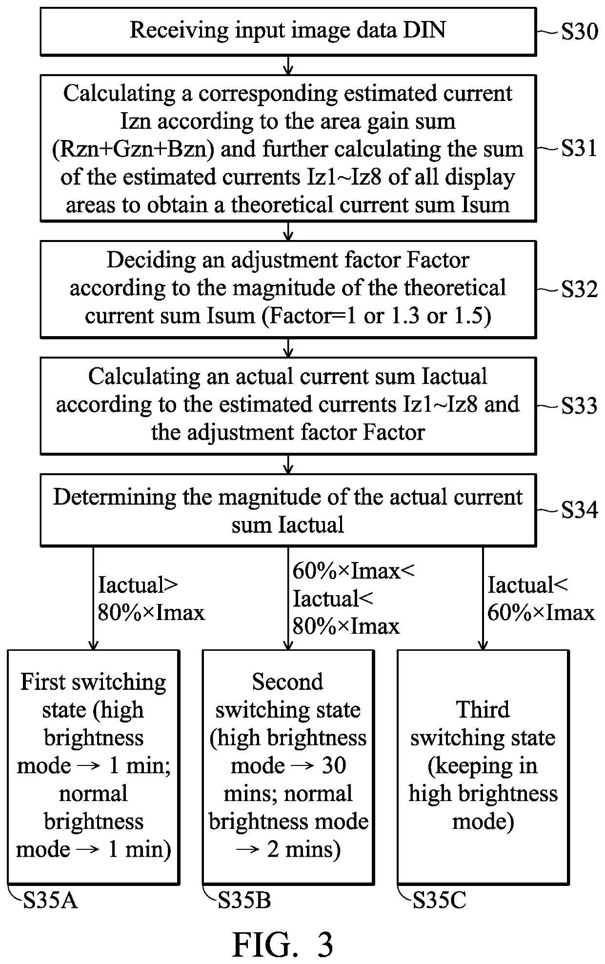
A display device is provided. The display device includes a display panel, a backlight controller, a light source module, and an image processor circuit. The display panel is divided into display regions. The backlight controller generates driving signals according to control signals. The light source units in the light source module are controlled respectively by the driving signals to emit light. The image processor circuit generates the control signals according to input image data. The image processor circuit obtains a respective estimated current according to the sum of first and second color brightness gains of the pixel cells in each display region and further determines an adjustment factor according to the sum of all the estimated currents. When the backlight controller operates in a high brightness mode, the image processor circuit changes the control signals according to the adjustment factor, thereby adjusting the driving signals.

Description

CROSS REFERENCE TO RELATED APPLICATIONS[0001]This application claims priority of China Patent Application No. 201710817587.9, filed on Sep. 12, 2017, the entirety of which is incorporated by reference herein.BACKGROUNDField[0002]The disclosure relates to a display device, and more particularly to a display device performing a backlight driving method to provide backlight with high brightness.Description of the Related Art[0003]With the development of technology for image capture and display, high dynamic range imaging (HDR) technology is not only used for image capture but also gradually applied to displayers. According to the specification of the HDR technology, a panel of a displayer must support high brightness, high contrast, and local dimming to enhance the brightness and detail of the frames to provide the user with better viewing experience. In general, a backlight module of a display panel needs to be driven by a large driving current to achieve high brightness. However, dri...

Claims


Application Information

Patent Timeline
Patent Type & Authority Patents(United States)
IPC IPC(8): G09G5/10G09G3/36G09G3/34
CPCG09G3/342G09G3/36G09G5/10G09G2330/045G09G2320/062G09G2360/16G09G3/3406G09G3/3413
Inventor LI, YONG QIANG
Owner WISTRON CORP
Learn More