Ultra compact ultra broad band dual polarized base station antenna

a base station antenna and ultra-wideband technology, applied in the direction of polarised antenna unit combinations, radiating element structural forms, resonant antennas, etc., can solve the problem of becoming even more challenging

Active Publication Date: 2020-03-24
HUAWEI TECH CO LTD
View PDF15 Cites 0 Cited by
  • Summary
  • Abstract
  • Description
  • Claims
  • Application Information

AI Technical Summary

Benefits of technology

[0008]The design of the radiating element allows that the overall dimension of the radiating element as implemented in an ultra compact ultra broadband antenna is reduced. In particular, as the operational bandwidth of the radiating element is lower than the resonance frequency of the first dipole, the length of the dipole is actually reduced with respect to a conventional dipole antenna design.
[0024]In a sixteenth implementation of the radiating element according to the first aspect, the first and / or the second dipole include each two opposing dipole arms. Furthermore each two opposing dipole arms can be in the form of two opposing quadratic fields having a recess on the two outer corners of the two opposing quadratic fields. This allows a compact design of the radiating element.

Problems solved by technology

As it is well known, this becomes even more challenging when trying to reduce the overall geometrical antenna dimensions (compact design) and keeping RF KPIs.

Method used


Image

  • Ultra compact ultra broad band dual polarized base station antenna
  • Ultra compact ultra broad band dual polarized base station antenna
  • Ultra compact ultra broad band dual polarized base station antenna

Examples


Embodiment Construction

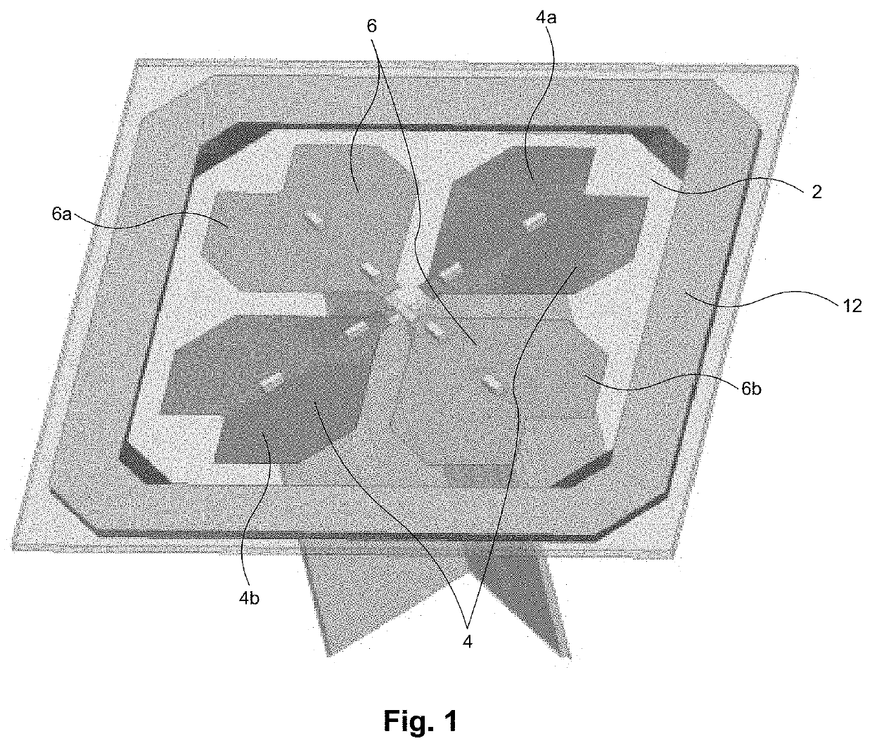
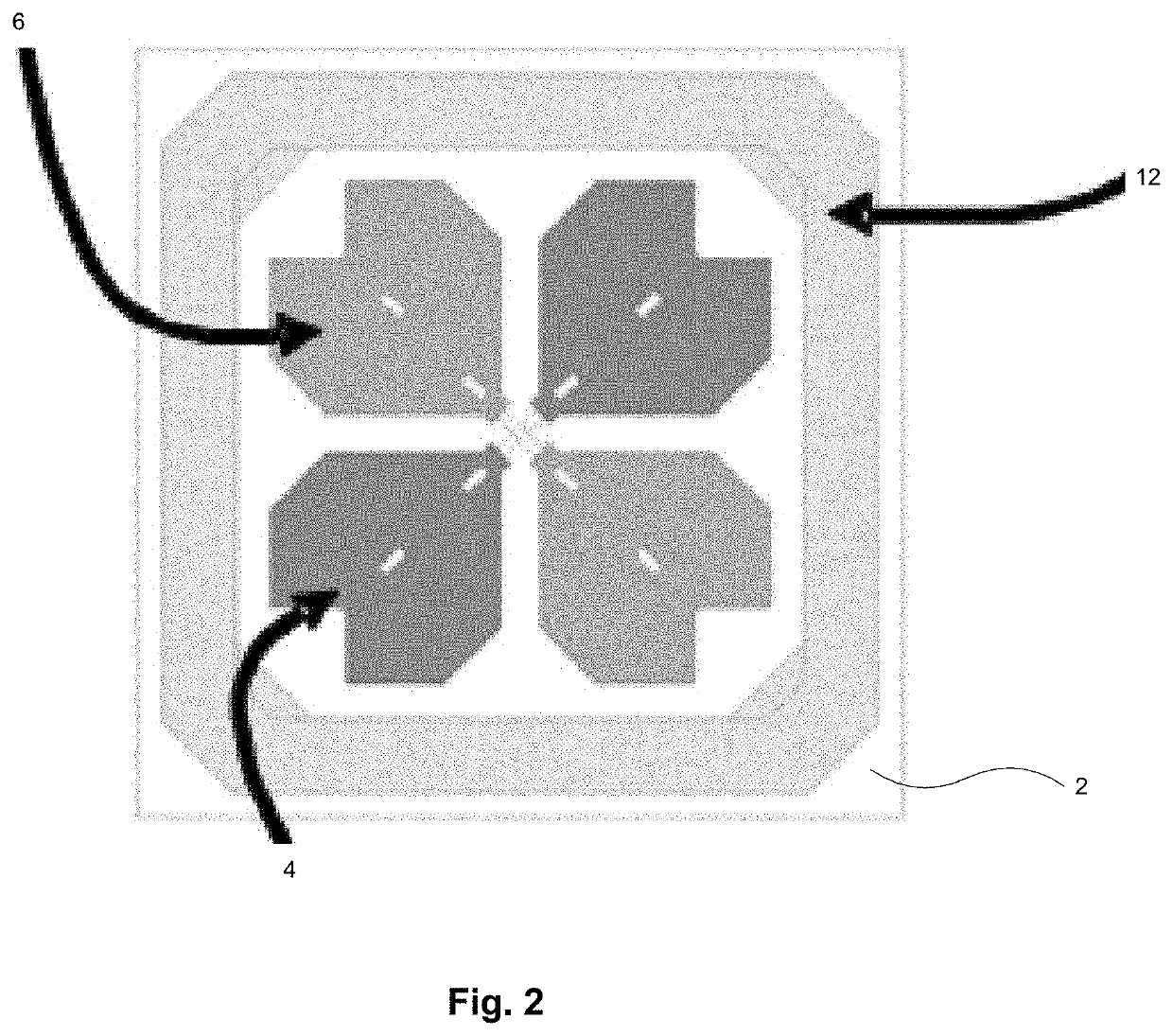
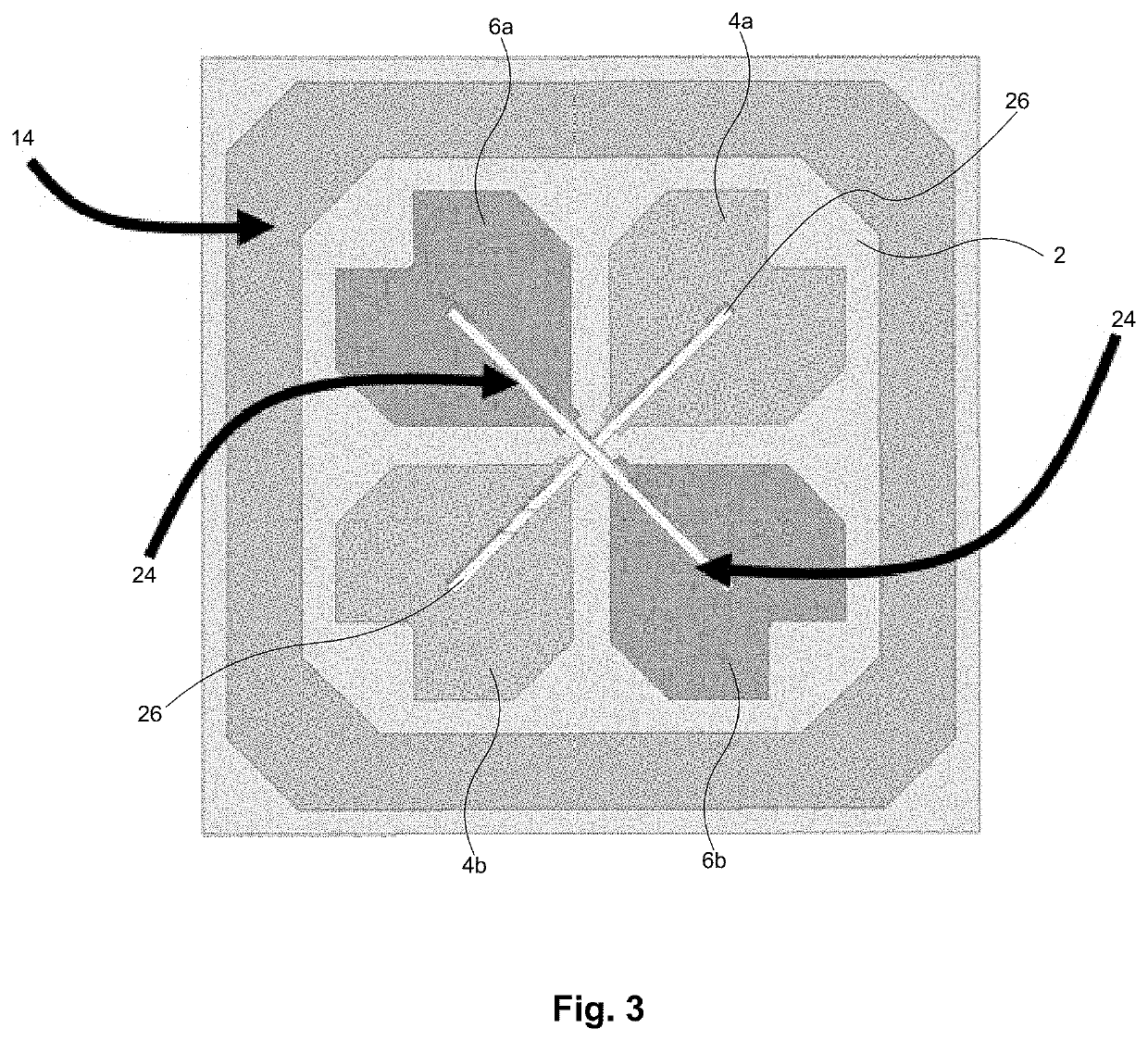
[0034]With reference to FIGS. 1 to 3 an embodiment of a radiating element is described. The radiating element includes a support structure 2 in the form of a quadratic PCB. On the top surface of the PCB 2 first and second dipoles 4 and 6 are located on a single layer. The first dipole 4 includes two opposing dipole arms 4a, 4b. The second dipole 6 includes two opposing dipole arms 6a, 6b. Just for illustration purposes, the PCB 2 is illustrated as transparent. The dipoles 4 and 6 are arranged perpendicular to each other. With reference to FIG. 7, an example of an electric polarisation of the dipole elements is indicated by arrows 8 and 10. A skilled person will understand that the dipoles can include any phase shift such that any linear or circular or elliptical polarized radiation field can be radiated from the radiating element.

[0035]The top surface of the PCB 2 also includes a ring 12 which in the present embodiment has the form of a square wherein the edges of the square are cut...


PUM


Abstract

The present disclosure refers to a radiating element comprising a support structure, a first dipole arranged on the support structure, and at least one electrically closed ring arranged on the support structure. The at least one electrically closed ring surrounds the first dipole and is galvanically isolated from the first dipole, and a resonance frequency of the first dipole is higher than a center frequency of an operational bandwidth of the radiating element.

Description

CROSS-REFERENCE TO RELATED APPLICATIONS[0001]This application is a continuation of International Application No. PCT / EP2016 / 077438, filed on Nov. 11, 2016, which claims priority to EP Patent Application No. EP15194746.2, filed on Nov. 16, 2015. The disclosures of the aforementioned applications are hereby incorporated by reference in their entireties.TECHNICAL FIELD[0002]The present invention relates to a radiating element, in particular, a radiating element of an antenna suitable for a base station, such as an ultra compact ultra broad dual polarized base station antenna.BACKGROUND[0003]Ultra broad band base station antenna systems typically operate in the 690-960 MHz (“Low Band”—LB) and 1.7-2.7 GHz (“High Band”—HB) spectrum which includes most cellular network frequency bands used today. With the growing demand for a deeper integration of antennas with Radios, e.g. Active Antenna Systems (AAS), new ways of designing ultra compact ultra broadband multiple arrays base station antenn...

Claims


Application Information

Patent Timeline
Patent Type & Authority Patents(United States)
IPC IPC(8): H01Q21/00H01Q1/38H01Q1/24H01Q21/24H01Q19/00H01Q9/28H01Q21/26H01Q15/14
CPCH01Q19/005H01Q9/28H01Q1/38H01Q21/24H01Q21/26H01Q1/246H01Q15/14H01Q9/16
Inventor BISCONTINI, BRUNOSEGADOR ALVAREZ, JUANFLAMINI, ROBERTOMALLEPEYRE, VINCENT
Owner HUAWEI TECH CO LTD
Why Eureka
Try Eureka