Wafer-shaped pilot-type valve

a pilot-type valve and wafer-shaped technology, which is applied in the direction of valve housings, valve operating means/release devices, mechanical devices, etc., can solve the problems of increased manufacturing costs, no pilot-type valve which is also wafer-shaped, and the valve itself is heavy-weighted, so as to enhance the operation efficiency and facilitate the mation

Active Publication Date: 2012-04-10
KANE KOUGYOU
View PDF14 Cites 0 Cited by
  • Summary
  • Abstract
  • Description
  • Claims
  • Application Information

AI Technical Summary

Benefits of technology

[0010]In summary, in the present invention, in the pilot-type valve, the valve box enclosing the main valve is sandwiched between the pipe flanges tightened to each other with the bolts and nuts. In addition, the connection end portions of the valve box to be connected with the pipe flanges and having an inlet and outlet for the pressurized fluid respectively are flangeless. As compared with a flanged valve, the total weight of the valve can be significantly reduced, and the inter-surface dimension (i.e. the dimension between the connection end portions) can be shortened, and the number of the bolts required for pipe installation can be reduced to half. In addition, the space for installing the valve box between the pipe members can be reduced, and the work required for pipe installation can be efficiently carried out. Further, the load applied to the pipe members in a completed pipe arrangement can be reduced, and the material costs required for the flanges can be eliminated and thus the manufacturing cost can be significantly reduced.
[0011]Further, the cover flange neck is extended upward from the valve box of the main valve, and includes in it a space for allowing the passage of a pressurized fluid. Then, only the valve stem connecting the main valve with the driving portion for controlling the opening of the main valve in accordance with the variation in the pressure fed from the pilot valve is passed through the space in the cover flange neck. To enable this cover flange neck to be passed through the interval between the bolts extended between the pipe flanges and adjacent to each other on the circumferences of the pipe flanges, the cover flange neck is restricted to form a restricted portion in a width smaller than the interval between the bolts which will differ depending on the kinds of the pipe flanges selected in accordance with the size of the valve. Specifically, the cover flange neck is restricted only at sites on the side walls corresponding to the adjacent bolts. When the valve is mounted in a sandwiched state between the pipe members having pipe flanges at their end portions, the restricted portion of the cover flange neck escapes the adjacent bolts extended between the pipe flanges. In this manner, the cover flange neck can pass through the interval between the adjacent bolts without obstructing the provision of the bolts. Thus, the bolts can be threaded through all the bolt holes of the pipe flanges without causing any problems. Then, by simply securing the bolts with nuts, the valve can be interposed between the pipe members without any difficulty.
[0012]According to the present invention even if the interval between the bolts differs depending on the kind of the pipe flanges standardized in accordance with the size of the valve and the interval is narrow, the bolts can be threaded through all the bolt holes of the pipe flanges without causing any problems. Then, by securing the bolts with nuts, the valve can be mounted between the pipe members without any difficulty. Even if the interval between the adjacent bolts for allowing the cover flange neck to pass therethrough is narrow and thus the cover flange neck is narrowed at sites corresponding to the bolts to form a restricted portion inside it, it is not required to narrow the cover flange neck in the direction along which the bolts are extended. Thus, the area for allowing the passage of the pressurized fluid which passes inside the cover flange neck at the site corresponding to the restricted portion can be sufficiently reserved without causing any trouble to the actuation of the main valve by the driving portion. As a result, the function as a pilot-type valve can be carried out more satisfactorily.
[0014]Therefore, according to the present invention, as described above, the connection end portions and the pipe flanges can be easily mated with each other into an air-tight state without requiring any labor. In a piping operation for a conventional wafer-shaped valve, in order to interpose a sealing member such as a gasket between the connection end portions and the pipe flanges, the sealing member has to be aligned in suspended state coaxially between the pipe flanges and the connection end portions having a diameter smaller than the pipe flanges, with supporting the valve so that the connection and portion of the valve should be coaxial with the pipe flange, to connect the connection end portions and the pipe flanges. This operation is very troublesome and requires much labor. The present invention has cancelled these troubles and significantly enhances the operation efficiency. Consequently, the practical effects of the present invention are enormous.

Problems solved by technology

However, there has been no pilot-type valve which is also wafer-shaped.
If the valve box enclosing the main valve has flanges as is the case described above, there arises a problem that not only the valve itself is heavy-weighted but also the manufacturing cost increases at least by the material cost for the flanges.

Method used


Image

  • Wafer-shaped pilot-type valve
  • Wafer-shaped pilot-type valve
  • Wafer-shaped pilot-type valve

Examples


Embodiment Construction

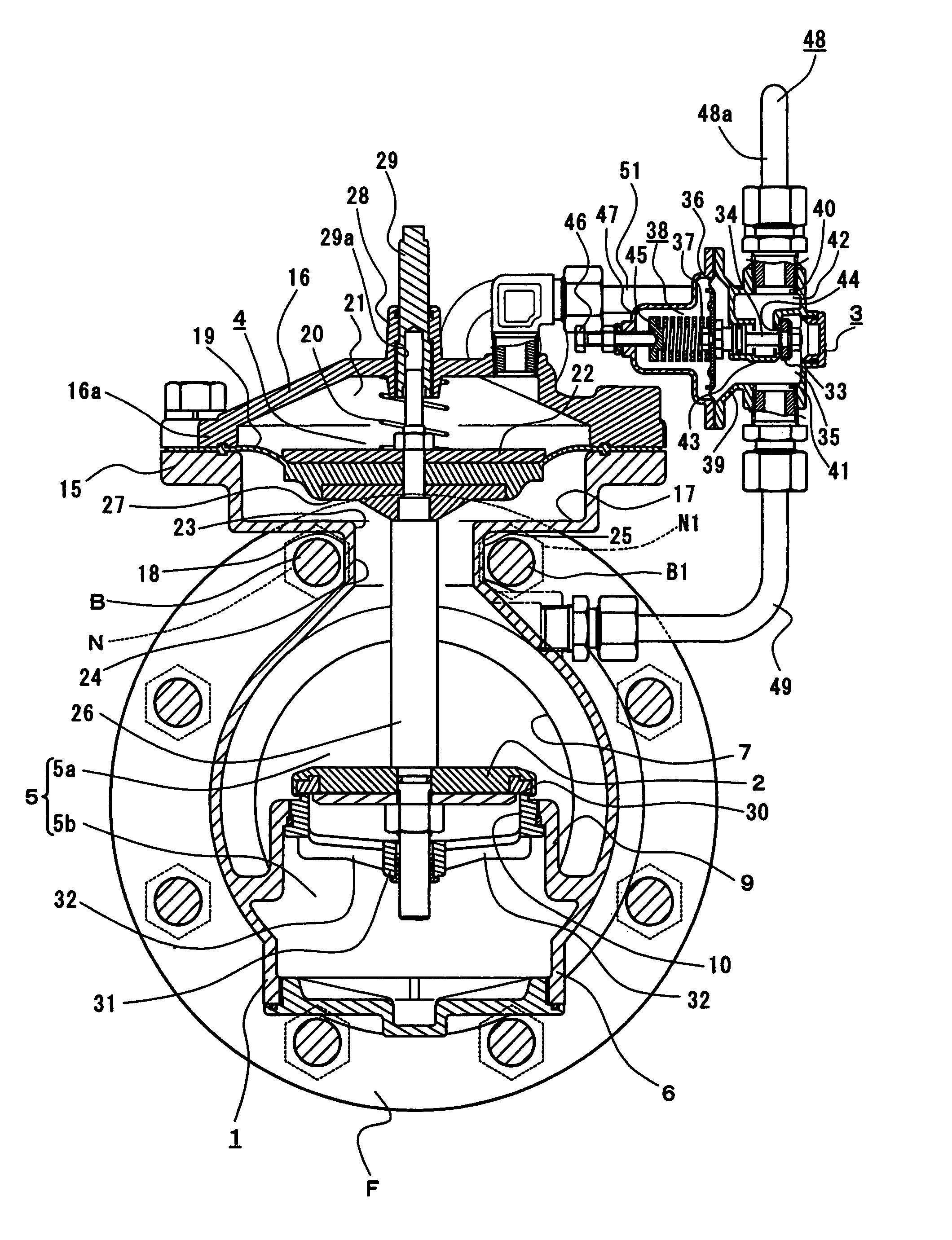
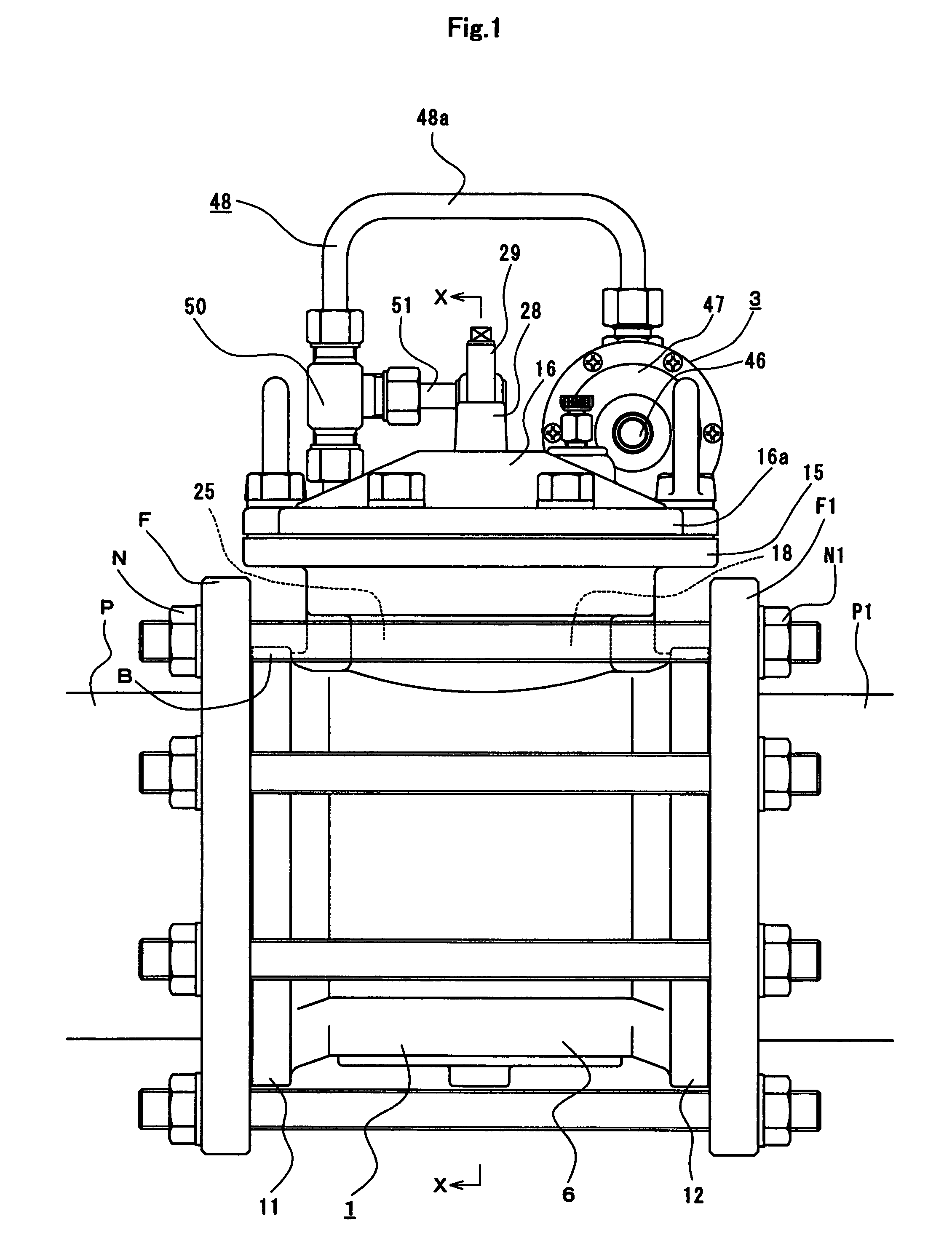
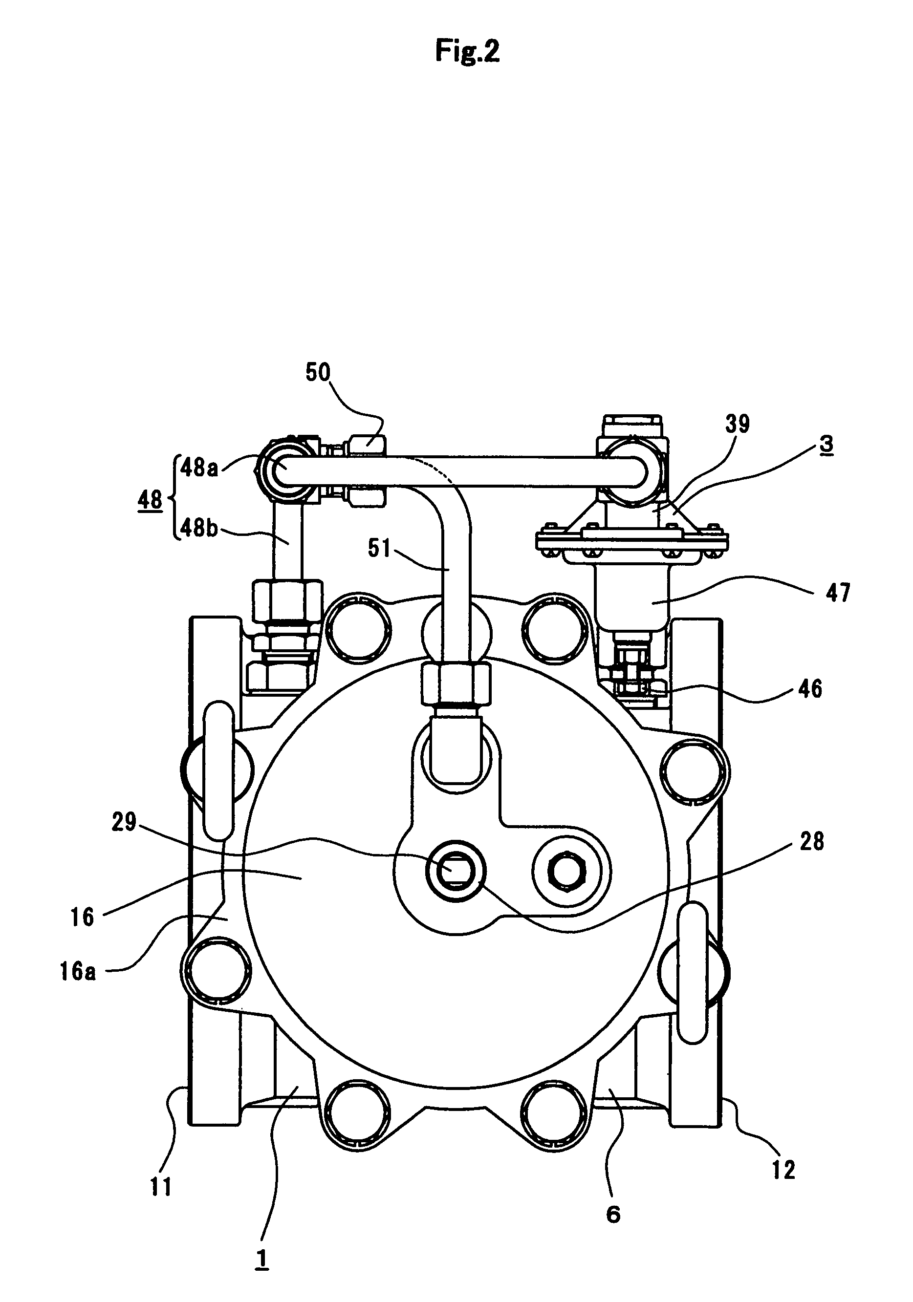
[0020]This valve is a pilot (acting) type valve that opens and closes its main valve 2 enclosed in a main body 1 by controlling a pilot valve 3 to increase and decrease a driving force (i.e. a pressure difference between a primary side-pressure and a secondary side-pressure) required to actuate the main valve 2. Specifically, the illustrated valve is a pilot-type pressure-reducing valve, whose main valve 2 enclosed in the main body 1 arranged in a main pipe operates using a pressure difference between the primary side-pressure and the secondary side-pressure as a driving force. A pressure-reducing valve with an opening small in diameter having a force balancing mechanism is used as a pilot valve 3. A pressure controlled through the pilot valve 3 is fed to a driving portion 4 of the main valve 2, so that the main valve 2 connected with the driving portion 4 opens and closes a flow path 5 included in the main body 1 and communicating with the main pipe.

[0021]The main body 1 includes a...


PUM


Abstract

In a pilot-type valve, a valve box enclosing a main valve is arranged in a state wherein same is sandwiched between pipe flanges tightened to one another with bolts. In the pilot-type valve, a pilot valve is used to control a driving force required to operate the main valve to open and close same. In addition, the valve box is flangeless at its connection end portions for connection with the pipe flanges and has an inlet and outlet for a pressurized fluid. A cover flange neck extended upward from the valve box is constricted only at sites on its walls corresponding to adjacent bolts extended between the pipe flanges, so that the cover flange neck can be passed through the interval between these bolts.

Description

BACKGROUND OF THE INVENTION[0001]1. Field of the Invention[0002]The present invention relates to a wafer-shaped pilot-type valve. The valve is a pilot acting valve that uses a pilot valve to control the opening and closing of a main valve, for example, a pressure adjustment valve such as a pressure reducing valve, an electromagnetic valve, and a water level regulating valve. A valve box of the main valve is sandwiched between pipe flanges and is fixed to this state by the bolts passing through the pipe flanges.[0003]2. Description of the Related Art[0004]Conventionally, there are wafer-shaped valves such as a single plate check valve and a flangeless butterfly valve. In these wafer-shaped valves, a thin discoid valve body swings or rotates inside a thin cylindrical valve box through which the flow of the fluid is regulated linearly, so as to open and close a flow path. These valves are relatively simple in structure and operation (for example, see Japanese Industrial Standards Commi...

Claims


Application Information

Patent Timeline
Patent Type & Authority Patents(United States)
IPC IPC(8): F16K31/12
CPCF16K31/1262F16K31/128F16K31/1266F16K27/0209G05D16/16F16K11/00F16K27/00
Inventor OCHIAI, MASARUTSUCHIMOTO, KATSUMI
Owner KANE KOUGYOU
Why Eureka
Try Eureka