Duplex snubbing jack

a snubbing jack and double-sided technology, applied in the direction of drilling pipes, wellbore/well accessories, sealing/packing, etc., can solve the problems of increasing the time and cost associated with a typical snubbing operation, new pipe lengths are not supported along their lengths, and the risk of buckling is reduced. , to achieve the effect of reducing the overall time required, reducing the risk of buckling, and reducing the cost associated

Active Publication Date: 2020-03-31
ODFJELL PARTNERS INVEST LTD
View PDF13 Cites 1 Cited by
  • Summary
  • Abstract
  • Description
  • Claims
  • Application Information

AI Technical Summary

Benefits of technology

[0011]Applicant proposes a duplex snubbing jack that will, among other advantages, minimize the risk of buckling a new length of pipe as it is being snubbed into a wellbore. Applicant's duplex snubbing jack will also reduce the overall time required for conducting a snubbing operation. These advantages of Applicant's snubbing jack will correspondingly reduce the cost associated with such snubbing operations.
[0012]In one embodiment Applicant's duplex snubbing jack is comprised of first or upper gripping unit and a second or lower gripping unit such as similarly configured first and second slip-type spiders. The first and second gripping units are positioned between a base frame and cap frame that are separated by a plurality of support rails. The base frame, cap frame, and the first and second gripping units each have central openings that are in co-axial alignment with each other. The base frame has a flange configuration around the central opening of the base frame that allows the duplex snubbing jack to be positioned in co-axial alignment onto or adjacent to a BOP stack or other wellhead device through which pipe may be inserted into a wellbore.
[0020]The gripping slips of the second or lower gripping unit are then closed as previously described to grip the new length of pipe and the attached wellbore pipe string while the gripping slips of the first upper gripping unit are synchronously opened as previously described to release the wellbore pipe string. The first or upper gripping unit and the second or lower gripping unit are then synchronously moved upwardly and downwardly, respectively, to their outmost position away from each other by extension of the jack rod of the first positioning linear actuator and retraction of the jack rod of the second positioning linear actuator. The downward movement of the second or lower gripping unit will further push the wellbore pipe string into the wellbore. This process may then be repeated to snub or run additional lengths of pipe into the wellbore.
[0023]The guide rails of the duplex snubbing jack support the length of pipe being snubbed along its entire length. The lateral support of pipe being snubbed provided by the guide rails will reduce the incidence of pipe buckling as the length of pipe is pushed through the BOP stack by the reciprocal movement of the gripping units.

Problems solved by technology

One problem associated with typical snubbing units is that the new length of pipe being snubbed into the wellbore is unsupported along its length when the new length of pipe is forced downward into the wellbore against the upward wellbore pressure by retraction of the piston rods of the hydraulic cylinders.
The compressive forces placed on the unsupported length of pipe during snubbing increases the risk that the new length of pipe will buckle as it is pushed through the internal seals of the pressure control equipment.
This increases the time and costs associated with a typical snubbing operation.
Another problem associated with typical snubbing units is time required for the travelling spider to move from the top of the piston stroke, the position where the piston rods of the hydraulic cylinders are extended and a new length of pipe is grabbed, to the bottom of the piston stroke, the position where the new length of pipe is released after it is pushed through the internal seals of the pressure control equipment, and then return to top of the piston stroke where another length of pipe may be grabbed.

Method used


Image

  • Duplex snubbing jack
  • Duplex snubbing jack
  • Duplex snubbing jack

Examples


Embodiment Construction

[0030]In the drawings, well established features that do not bear upon points of novelty are omitted in the interest of descriptive clarity. Such omitted features may include threaded junctures, weld lines, sealing elements, pins, and the like.

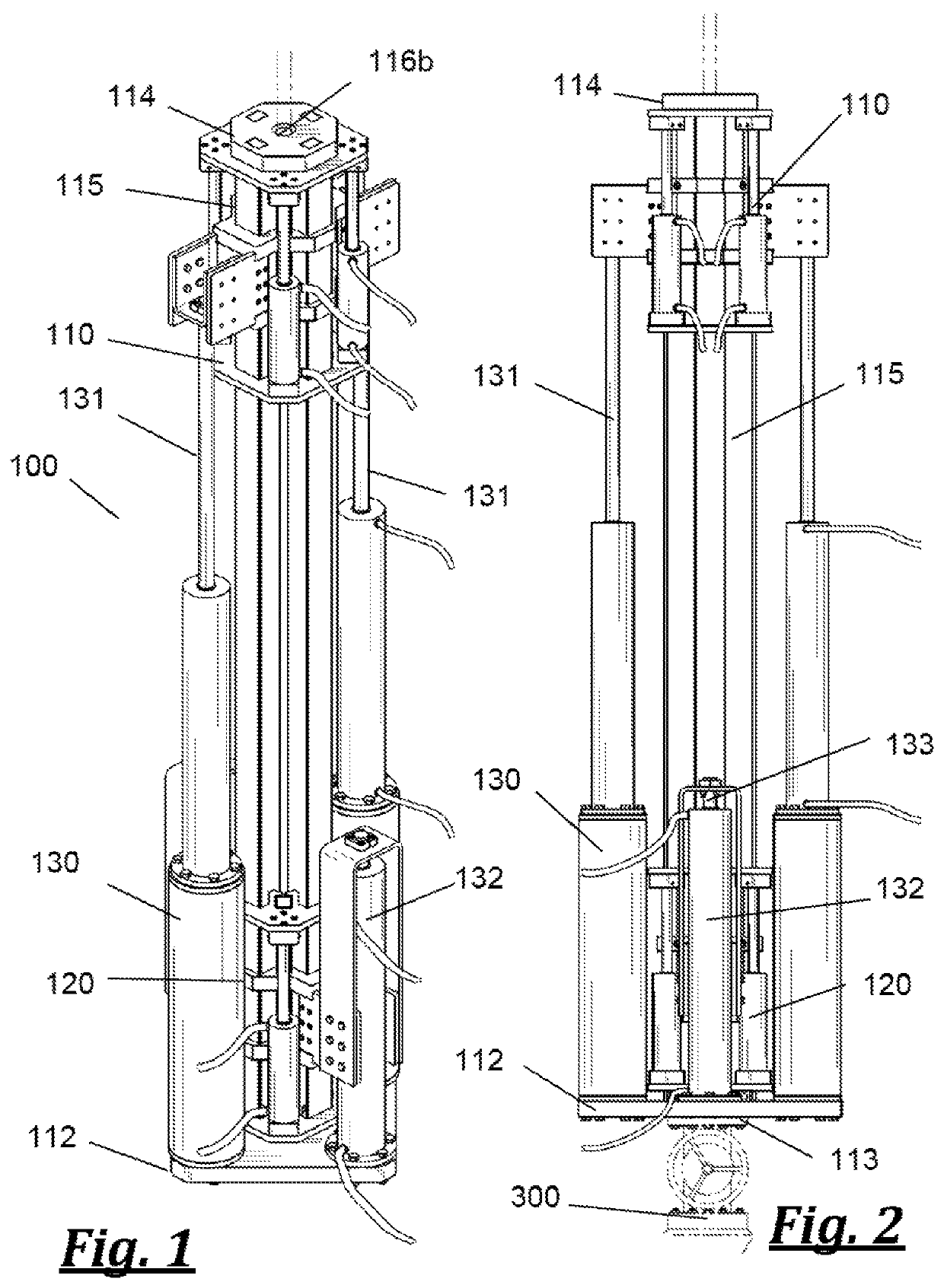
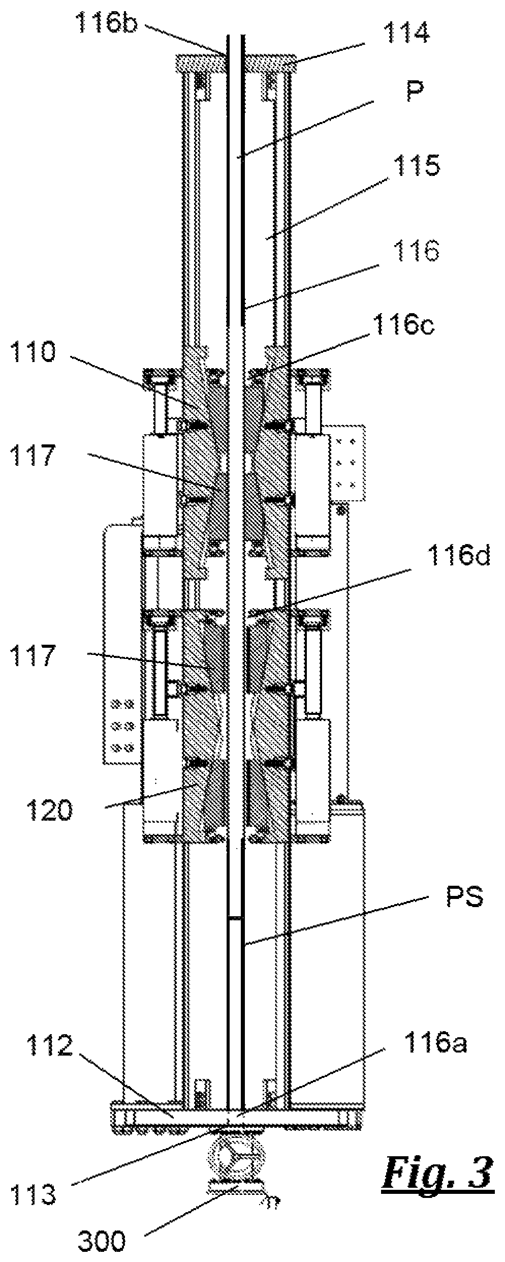
[0031]FIGS. 1 through 3 show an embodiment of the duplex snubbing jack (100). As shown, the duplex snubbing jack (100) has a first or upper pipe gripping unit (110) and a second or lower pipe gripping unit (120). The pipe gripping units (110) and (120) are shown as similarly configured slip-type pipe gripping units but other types of pipe gripping units or assemblies might also be utilized. The pipe gripping units (110) and (120) are positioned between a base to (112), which may be a base plate as shown or a framework of structure members such as beams and plates, and a cap (114), shown as a plate but which may also be a framework of structure members such as beams and plates, that are separated by a plurality of support rails (115).

[0032]The ...


PUM


Abstract

A duplex snubbing jack and method of snubbing pipe into a well bore which includes first and second gripping units that alternately and synchronously grip and release a length of pipe to be attached to a pipe string. The first and second gripping units are synchronously movable upward and downward toward and away from each other to push or pull the pipe through a BOP stack and into or out of a wellbore. Linear actuators are used to synchronously move the first and second gripping units. Guide rails are provided to laterally support the pipe as the pipe is pushed or pulled through the BOP stack into or out of the wellbore. The first and second gripping units are preferably slip-type spiders.

Description

PRIORITY[0001]This application claims priority to U.S. provisional application Ser. No. 62 / 398,370 filed Sep. 22, 2016 entitled “Duplex Snubber”, the entire contents of which is hereby incorporated by reference.FIELD OF THE INVENTION[0002]This invention relates to drilling and production of oil and gas. More specifically, the invention relates to an improved snubbing tool for use in inserting pipe or other tubing into live wells under pressure.BACKGROUND[0003]The wellbore pressure of an oil and as well is usually contained by pressure control equipment having resilient internal seals that seal the wellbore opening around the wellbore tubing string. Snubbing is the process of attaching a length of pipe or tubing onto the wellbore tubing string and inserting or advancing the wellbore pipe string with the newly attached length of pipe into the wellbore when the wellbore is under pressure. Snubbing often requires significant downward force on the wellbore pipe string in order to push an...

Claims


Application Information

Patent Timeline
Patent Type & Authority Patents(United States)
IPC IPC(8): E21B19/086E21B19/00E21B19/08E21B19/16E21B19/083E21B19/24E21B19/10E21B33/068E21B33/06
CPCE21B19/083E21B19/086E21B19/24E21B19/10E21B33/068E21B33/06
Inventor SIPOS, DAVID L.
Owner ODFJELL PARTNERS INVEST LTD
Why Eureka
Try Eureka