Honeycomb structure

a honeycomb and structure technology, applied in the field of honeycomb structure, can solve the problems of increasing reducing the output of the engine or degrading the fuel consumption, and increasing the pressure loss in the honeycomb structure, so as to suppress the deterioration of strength, promote the diffusion of exhaust gas, and improve purification performance

Active Publication Date: 2020-03-31
NGK INSULATORS LTD
View PDF4 Cites 0 Cited by
  • Summary
  • Abstract
  • Description
  • Claims
  • Application Information

AI Technical Summary

Benefits of technology

[0005]In the above NOx treatment by the honeycomb structure, it is possible to improve the ability to purify the exhaust gas by loading the honeycomb structure with an increased amount of catalyst. Meanwhile, when a honeycomb structure loaded with catalyst is installed in the exhaust system of a diesel-fueled vehicle, for example, for NOx treatment, this may cause a problem of an increase of pressure loss in the honeycomb structure. Such an increase of pressure loss in the honeycomb structure may reduce the output from the engine or degrade the fuel consumption.
[0006]As another method to improve the purifying performance, the cell density of a honeycomb structure may increase so as to increase the ratio of contact of catalyst with exhaust gas. Such an increase of cell density of the honeycomb structure, however, may lead to the problem of an increase of pressure loss in the honeycomb structure.
[0007]In order to improve the temperature-rising property and the loading amount of catalyst of the honeycomb structure, a technique of increasing the porosity of the partition wall of the honeycomb structure also has been proposed. Such a honeycomb structure with increased porosity of the partition wall is intended to suppress an increase of the pressure loss while increasing the amount of catalyst for loading, for example. Such a honeycomb structure with increased porosity of the partition wall, however, has reduced mechanical strength of the honeycomb structure. In this way, there is a limit to increase the porosity of the partition wall, and the current techniques have a difficulty to improve the purifying performance more.
[0008]In view of such problems of the conventional techniques, the present invention provides a honeycomb structure capable of improving the purifying performance while keeping the cell density of the honeycomb structure without increasing it and suppressing deterioration of the strength.
[0015]Advantageously the honeycomb structure of the present invention can be favorably used as a catalyst carrier to be loaded with catalyst for purifying of exhaust gas and can improve the purifying performance while suppressing deterioration of the strength. Specifically the plurality of cells surrounded by the porous partition wall include partially clogged cells, and each of the partially clogged cells includes a protrusion that protrudes inward of each of the partially clogged cells from the surface of the partition wall that surrounds each of the partially clogged cells. When exhaust gas passes through the clogged part of each cell having the protrusion, this part can promote diffusion of the exhaust gas and can improve the purifying performance. The protrusion also can increase the contact area between the catalyst on the surface of the partition wall and the exhaust gas, and so can improve the purifying performance. The ratio of number of the partially clogged cells to the total number of cells and the area ratio of the protrusion in each of the partially clogged cells may be set within predetermined numerical ranges, whereby the purifying performance as stated above can improve while effectively suppressing deterioration of the strength.

Problems solved by technology

Meanwhile, when a honeycomb structure loaded with catalyst is installed in the exhaust system of a diesel-fueled vehicle, for example, for NOx treatment, this may cause a problem of an increase of pressure loss in the honeycomb structure.
Such an increase of pressure loss in the honeycomb structure may reduce the output from the engine or degrade the fuel consumption.
Such an increase of cell density of the honeycomb structure, however, may lead to the problem of an increase of pressure loss in the honeycomb structure.
Such a honeycomb structure with increased porosity of the partition wall, however, has reduced mechanical strength of the honeycomb structure.
In this way, there is a limit to increase the porosity of the partition wall, and the current techniques have a difficulty to improve the purifying performance more.

Method used


Image

  • Honeycomb structure
  • Honeycomb structure
  • Honeycomb structure

Examples


example 1

[0052]10 parts by mass of pore former, 1 part by mass of organic binder and 30 parts by mass of dispersing medium were added to 100 parts by mass of the cordierite forming raw material, followed by mixing and kneading to prepare a kneaded material. As the cordierite forming raw material, alumina, aluminum hydroxide, kaolin, talc, and silica were used. As the pore former, hollow resin particles were used. As the organic binder, methylcellulose was used. As the dispersing medium, water was used.

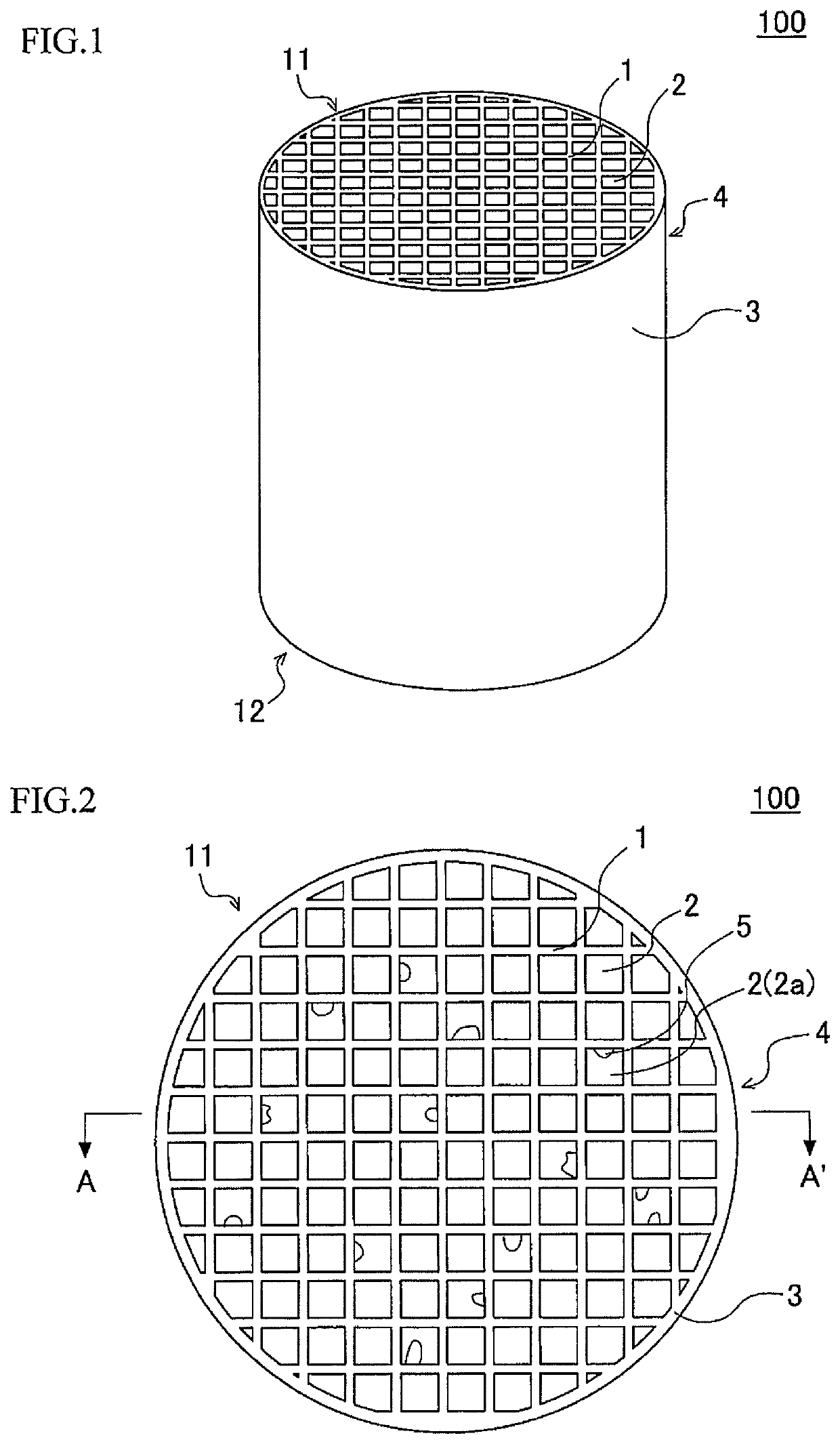
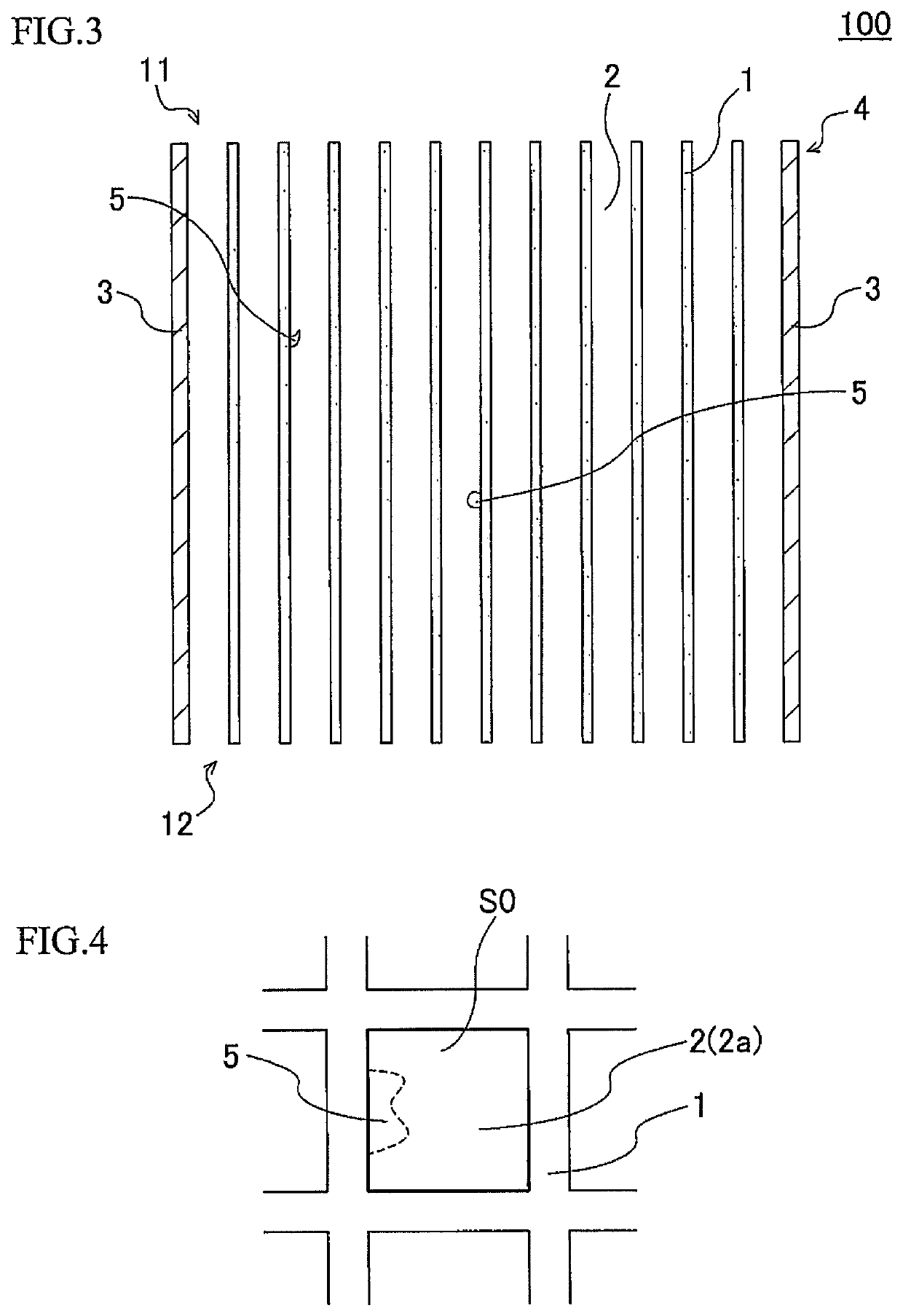
[0053]Next, the kneaded material was extruded using a die for manufacturing of a honeycomb formed body to have a honeycomb formed body having a round pillar shape as the overall shape. The cells of the honeycomb formed body had a quadrangular shape.

[0054]Next, this honeycomb formed body was dried by a microwave dryer, and then was dried completely by a hot-air drier, and then both end faces of the honeycomb formed body were cut so as to have predetermined dimensions. Next the dried honeycomb fo...

examples 2 to 9

, Comparative Examples 1 to 8

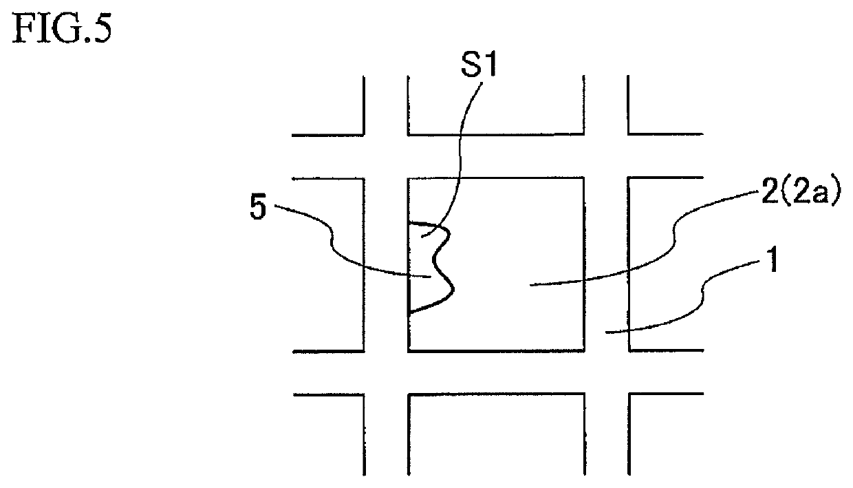
[0073]The honeycomb structures of these Examples and Comparative Examples were manufactured similarly to Example 1 other than that the configuration of these honeycomb structures was changed as shown in Table 1. The area ratio of protrusions and the ratio of number of partially clogged cells were adjusted by changing the amount of water to prepare the kneaded material variously within in the range of 65 parts by mass or less so as to change the state of formation of the surface of the partition wall of each of the honeycomb formed bodies during extrusion.

[0074]For the honeycomb structures of Examples 2 to 9 and Comparative Examples 1 to 8, the “NOx purifying ratio (%)”, “isostatic strength (MPa)” and “compressive strength (MPa)” were measured similarly to Example 1. Table 2 shows the result.

[0075](Results)

[0076]The honeycomb structures of Examples 1 to 9 successively improved the NOx purifying performance as compared with the honeycomb structure of Compa...


PUM

PropertyMeasurementUnit
thicknessaaaaaaaaaa
thicknessaaaaaaaaaa
lengthaaaaaaaaaa

Abstract

A honeycomb structure includes a porous partition wall disposed so as to surround cells extending from a first end face to a second end face. The cells include partially clogged cells which account for 10 to 80% of the total number of the cells, and each of which includes a protrusion that protrudes inward from the surface of the partition wall. The protrusion is partially formed in a direction in which each partially clogged cell extends. In a projected view from the first end face to the second end face, a ratio of area of the protrusion in each partially clogged cell to whole area of the through channel of each partially clogged cell is 5 to 80%, the whole area including the protrusion, and the partition wall surrounding each partially clogged cell has a thickness at a thinnest part of 0.038 mm or more.

Description

[0001]The present application is an application based on JP 2018-062667 filed on Mar. 28, 2018 with Japan Patent Office, the entire contents of which are incorporated herein by reference.BACKGROUND OF THE INVENTIONField of the Invention[0002]The present invention relates to honeycomb structures. More specifically the present invention relates to a honeycomb structure capable of improving the purifying performance while suppressing deterioration of the strength.Description of the Related Art[0003]Developed countries are examining to tighten the standards on NOx emission from diesel-fueled vehicles and tracks more. To meet such NOx emission standards, various techniques have been proposed to treat NOx in exhaust gas. One of these techniques is, for example, loading a honeycomb structure having a porous partition wall with Selective Catalytic Reduction catalyst (hereinafter this may be called “SCR catalyst”), for example, and treats NOx in exhaust gas for purification with the honeycom...

Claims


Application Information

Patent Timeline
Patent Type & Authority Patents(United States)
IPC IPC(8): F01N3/28B01J35/10B01J35/04
CPCB01J35/10F01N3/2842B01J35/04F01N2330/38F01N2330/48F01N3/2803F01N2330/06F01N3/2828Y02A50/20
Inventor KURIMOTO, YUDAIHIROSE, SHOGO
Owner NGK INSULATORS LTD
Why Eureka
Try Eureka