Eureka AIR delivers breakthrough ideas for toughest innovation challenges, trusted by R&D personnel around the world.

Optical time-domain reflectometer (OTDR) with integrated, retractable launch cable

a technology of optical time domain reflectometer and launch cable, which is applied in the direction of instrumentation, optical/optical waveguide device testing, structural/machine measurement, etc., can solve the problems of affecting the value of otdr, affecting the resolution, and the lowest-reflectance fiber optic connector available today has some loss and reflectance, so as to facilitate the detachment and replacement of the launch cable

Active Publication Date: 2020-03-31
LIFODAS
View PDF6 Cites 0 Cited by
  • Summary
  • Abstract
  • Description
  • Claims
  • Application Information

AI Technical Summary

Benefits of technology

[0014]Two key features of this invention are first, the OTDR and Launch Cable (with flying lead) are contained by a single housing and second, the OTDR and Launch Cable are connected (rather than fusion spliced) to each other making it possible for users to easily detach and replace the Launch Cable in the field, should it become damaged or worn out. A third key feature is the integration of wireless remote control technology so that the test instrument can be operated by an external device such as a smartphone, tablet, or PC.
[0017]Easier and faster to set up since the OTDR and launch cable can remain connected even when the instrument is packed for storage or transport.
[0023]Simpler, less costly processors in the OTDR since most calculations can be made by the external device.
[0024]Ability for remote users or servers to control and collect data from the OTDR via internet connections.The present invention also includes special embodiments in which the OTDR is physically contained within the launch cable and flying lead assembly, making the instrument more compact and resistant to impact damage.

Problems solved by technology

In addition, OTDR value is impacted by its price and user experience factors such as size, weight, and ease of use.
Resolution is also impacted by event loss and reflectance.
However, the best quality, lowest-reflectance fiber optic connectors available today have some loss and reflectance.
Because such long jumpers would be hard to use and expensive, OTDR manufacturers and other vendors offer special test cord assemblies called Launch Cables, which comprise a coil of optical fiber, enclosed in a protective housing, with connectorized flying leads—in effect one half of a fiber optic jumper—at each end, and a total connection-free fiber length sufficient to ensure accurate measurement of the first link connection.
One problem of this solution is that it requires the OTDR user to carry a separate box with their OTDR.
In addition, each time the OTDR is unpacked for use, this launch cable embodiment must be connected to the OTDR test port thus exposing the OTDR test port and a launch cable connector to unnecessary wear and possible damage if the two connectors are not cleaned properly before they are connected.
However this solution presents a new and significant problem.
Because the SFTM is fusion spliced to the OTDR there is no easy way for users to replace this module in the event that its flying lead (jumper), or the connector on this lead, becomes damaged through misuse, or simply worn out over time from normal use.
However, this embodiment suffers the same problem as the one noted above.
Because it is fusion-spliced to the OTDR it cannot be replaced easily.
In addition, because no flying lead is provided, this solution can only be used to test links with end cables that are not terminated in a patch panel.

Method used


Image

  • Optical time-domain reflectometer (OTDR) with integrated, retractable launch cable
  • Optical time-domain reflectometer (OTDR) with integrated, retractable launch cable
  • Optical time-domain reflectometer (OTDR) with integrated, retractable launch cable

Examples


Embodiment Construction

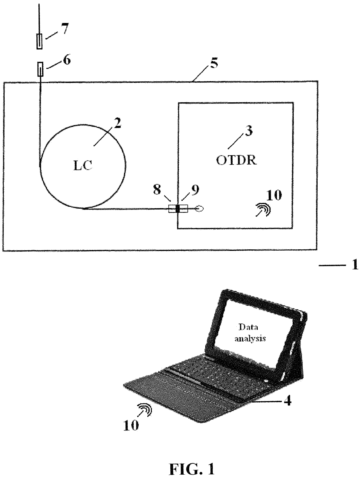
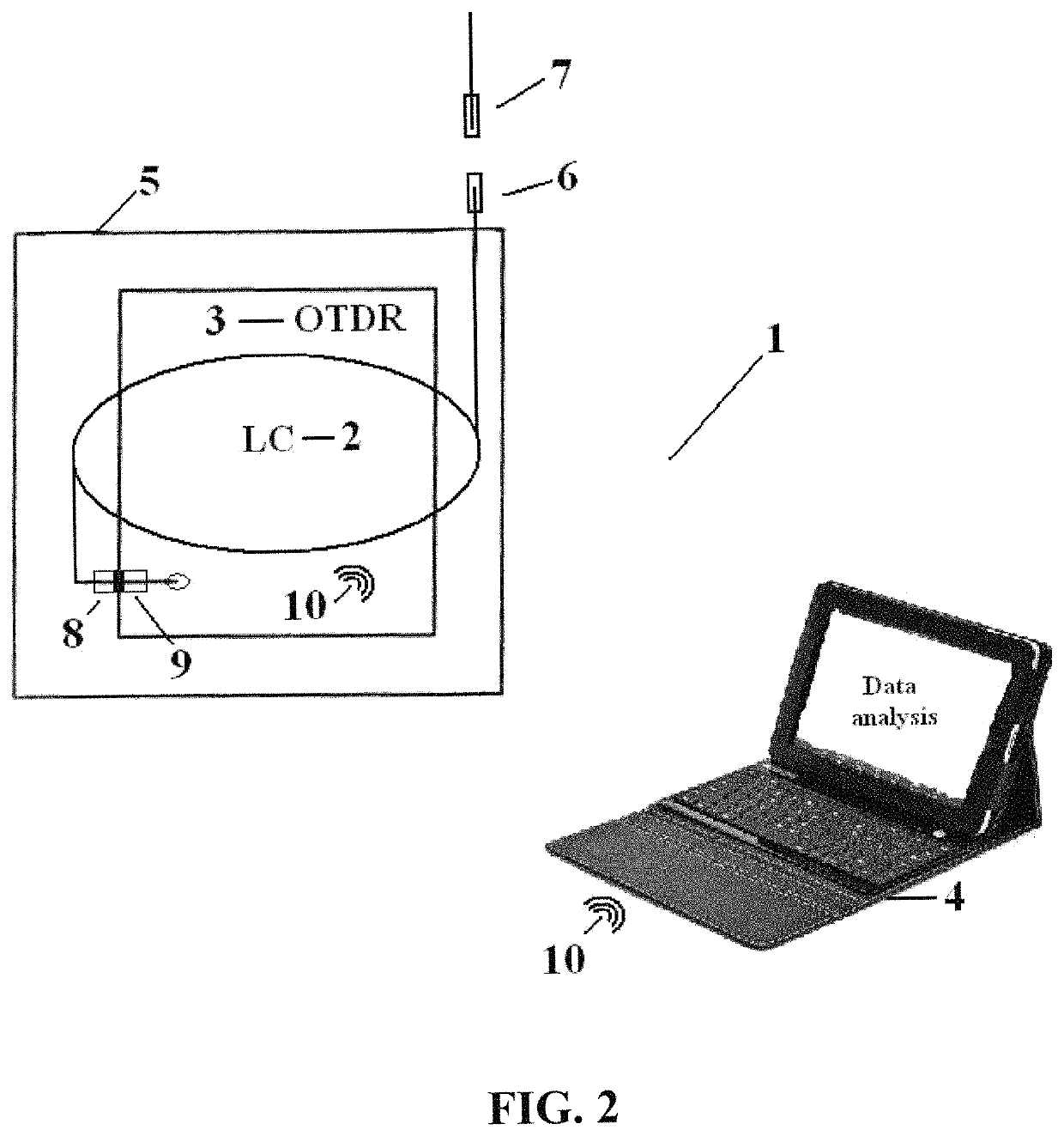
[0029]In FIG. 1, an Optical Time-Domain Reflectometer (OTDR) with an integrated but detachable Launch Cable, designed to work as standalone instrument or as a Remote Unit (RU) with external devices, is shown (1), which is an object of the present invention and will be referred to simply as Device (1) of this invention. In one of its OTDR modes, device (1) can be used to certify or fault locate FTTx PON or point-to-point fiber optic links that may include features or events such as fiber optic connections, fusion splices, mechanical splices, and optical splitters, in addition to faults such as optical fiber cable breaks and macrobends. Device (1) OTDR measurements may include end-to-end link loss and ORL, as well as the location, loss, and reflectance of individual events (including the first link connection). Without removing the launch cable, Device (1) may also be used in light source mode to measure end-to-end link loss at multiple wavelengths, or in visual fault locate (VFL) mod...


PUM


Abstract

The present invention is an Optical Time-Domain Reflectometer (OTDR) with an integrated Launch Cable that has a retractable lead, designed to work as a standalone instrument, or under the control of an external device such as a smartphone, tablet, PC, or server.The first characterized feature of this invention is the integration of the OTDR and Launch Cable in one housing where the spool of the aforementioned Launch Cable can rotate and is spring-loaded relative to the aforementioned housing, and is equipped with a flying lead that can be extracted from or retracted back into the aforementioned housing under spring tension, or where the spool of the aforementioned Launch Cable is affixed to the aforementioned housing and equipped with a flying lead that can be manually unwrapped from and wrapped back into the aforementioned housing; the OTDR and Launch Cable are attached, for example using standard fiber optic connectors, so that the Launch Cable can be easily replaced in the field by a user with no special tools.The second characterized feature of this invention is to integrate a wireless transmitting and receiving device into the OTDR module, which can receive setup and other commands from, and send instrument status and test results to an external device.The advantages of such a device are: the ability to conveniently hold, place, or hang the instrument as a single unit while in use; the ability to place the instrument into its carry case without disconnecting the launch cable, thus reducing the number of connection, cleaning, and inspection steps that must be performed each time the instrument is removed from its carry case for use and reducing wear on the OTDR test port and launch cable (OTDR end) connectors; the ability to remove and replace Launch Cable module in the field without special tools should it become damaged or if the user wants a different connector type; the ability to use an external device to analyse and format test results and provide additional networking functions; the ability to move processing functions to the external device, which in turn allows the use of lower power, lower cost processors in the OTDR to reduce cost and increase battery life. The present invention also includes a special embodiment in which the OTDR module is physically located within the Launch Cable module so that the overall device becomes more compact, and more resistant to drops and other external impacts.

Description

FIELD OF THE INVENTION[0001]The present invention relates to the Optical Time Domain Reflectometer (OTDR), a test instrument designed to certify and fault locate fiber optic links.BACKGROUND OF THE INVENTION (TECHNICAL LEVEL)[0002]To test a given fiber optic link, an OTDR is connected to one end of this link and then set up to inject a series of light pulses into the link while sampling (measuring) returned light power as a function of time. Returned light is composed of (Rayleigh) backscatter from the optical fiber sections comprising the link and (Fresnel) reflections from connections, splitters, breaks, or other events within the link. By converting sample times into distances based the estimated speed of light in optical fiber, the OTDR can create a graphic representation of link insertion loss as a function of distance and the reflectance of link events.[0003]OTDR performance is generally specified in terms of measurement accuracy, measurement range, ability to resolve and meas...

Claims


Application Information

Patent Timeline
Patent Type & Authority Patents(United States)
IPC IPC(8): G01M11/00G02B6/44
CPCG01M11/3154G02B6/4457G01M11/3145
Inventor LEVIN, PIOTR ANATOLIJ
Owner LIFODAS
Why Eureka
Eureka Blog
Learn More