Rotary cleaning device on bottom of dust collector

A technology for cleaning devices and vacuum cleaners, which is applied to cleaning equipment, machine parts, cleaning machinery, etc., and can solve the problems of easily scratched ground materials, consumption of cleaning power, adhesion of dust and sticking, etc.

Inactive Publication Date: 2017-10-27
杨雅菁
View PDF7 Cites 5 Cited by
  • Summary
  • Abstract
  • Description
  • Claims
  • Application Information

AI Technical Summary

Problems solved by technology

The operation mode of the traditional cleaning machine is mainly driven by a built-in motor to rotate a rotating disk. Several bundle brushes are extended from the periphery of the rotating disk. Most of them are made of nylon material. When the rotating disk rotates, the bundles The brush is in contact with the floor for cleaning and polishing, but the effect is not good and it is easy to scratch the floor material
In addition, each rotating disk needs to be pivotally connected to the rotating motor inside the cleaning machine, and it can be rotated independently by the power provided by the corresponding motor. Increase assembly and production costs, and consume too much power of the cleaning machine, and too many power transmission devices increase the risk of failure
In addition, the movement of the traditional automatic cleaning machine is achieved by the rollers arranged on the left and right sides of the bottom, and the rotating disk is arranged in front of the rollers. Dust will adhere to the ground and stick to the ground, and the rotating disc in front of the roller cannot effectively clean the traces and dirt produced by the roller during operation

Method used


Image

  • Rotary cleaning device on bottom of dust collector
  • Rotary cleaning device on bottom of dust collector
  • Rotary cleaning device on bottom of dust collector

Examples


Embodiment Construction

[0056] The present invention will be further described below in conjunction with the accompanying drawings and specific embodiments, so that those skilled in the art can better understand the present invention and implement it, but the examples given are not intended to limit the present invention.

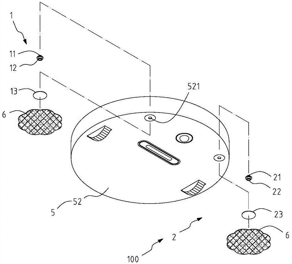
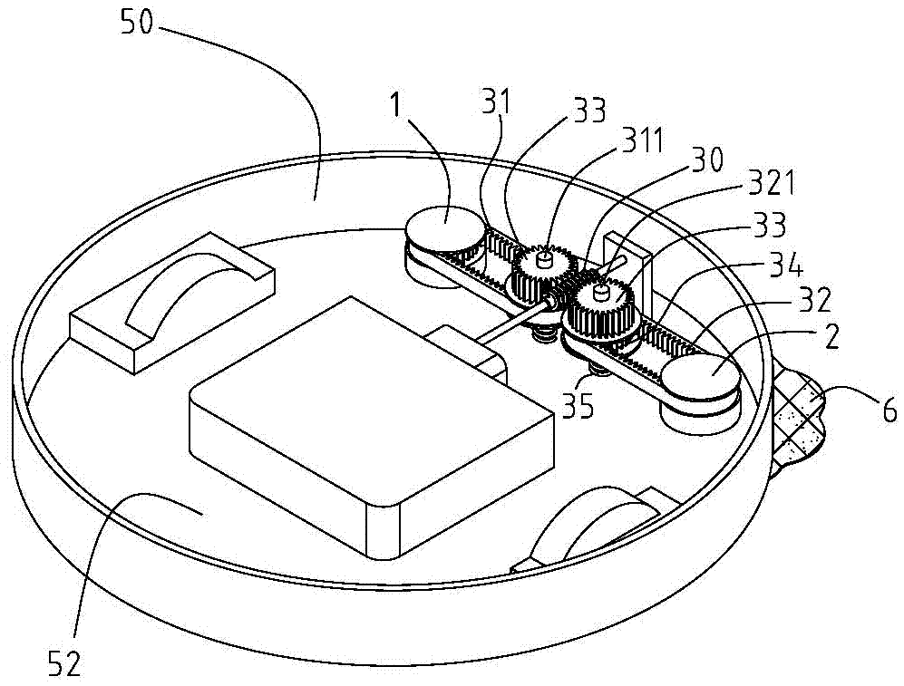
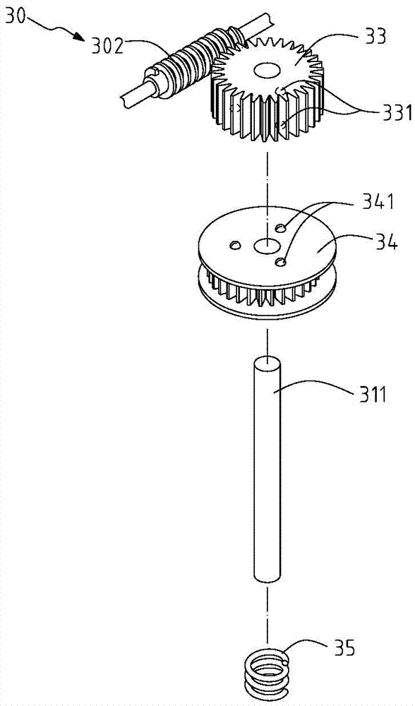
[0057] see Figure 1 to Figure 4 It is a preferred embodiment of the cleaning device 100 at the bottom of the vacuum cleaner of the present invention. The vacuum cleaner 5 of the present invention can be a self-propelled vacuum cleaner, and an accommodating space is formed by the bottom 52 of the upper cover 50, which is equipped with a motor 51, which is located in the center of the accommodating space 50 and is close to the end of the vacuum cleaner 5, which can be used to provide dust suction, and can also be used to drive the rotary cleaning device 100 of the present invention (details As described later), but the rotary cleaning device 100 of the present invention can also be...


PUM


Abstract

The invention discloses a rotary cleaning device for the bottom of a vacuum cleaner, which is detachably assembled on the bottom of the vacuum cleaner. An accommodating space is formed inside the vacuum cleaner and a motor is installed inside. The rotary cleaning device includes a first turntable, a second turntable, a transmission unit and at least two dust removal components. The shaft includes an upper end and a lower end. The upper end penetrates the bottom of the vacuum cleaner and is located in the accommodating space. A guide rail is formed around the upper end, and the lower end is connected with a fixing portion. One side of the substrate is connected to the fixing part, and the other side is connected to the dust removal assembly. The transmission unit includes a transmission shaft, a first transmission part and a second transmission part. The first and second transmission parts drive the first turntable and the second turntable to rotate through the transmission shaft, so that the dust removal component rotates to clean and wipe a foreign object . The rotary cleaning device provided by the present invention can utilize the original structure of a vacuum cleaner, be detachably assembled in the vacuum cleaner, and achieve the effect of cleaning and wiping through the rotation of an easily replaceable dust removal component.

Description

technical field [0001] The invention relates to a cleaning device for the bottom of a vacuum cleaner, in particular to a rotary cleaning device that is easy to assemble and disassemble, can be flexibly configured, and can reduce power burden through interlocking transmission. Background technique [0002] The first task of floor cleaning is to clean the floor first. Traditional cleaning uses a broom to clean manually, or you can use a rag to wipe it one by one, but both of them consume a lot of energy and time. Although vacuum cleaners can be used for vacuuming, traditional vacuum cleaners also need to be manually cleaned. Hand-held operation moves, time consumption is still inevitable. [0003] In order to improve the efficiency of pre-cleaning work, some operators have developed automatic cleaning machines with dust suction function, which use the movement of the machine to make the bottom of the machine suck in dust, or can be equipped with brush tools to use the bristles...

Claims


Application Information

Patent Timeline
Patent Type & Authority Applications(China)
IPC IPC(8): A47L11/24A47L11/283A47L11/40
CPCA47L11/24A47L11/283A47L11/40A47L11/4038A47L11/4069A47L11/4094
Inventor 杨雅菁
Owner 杨雅菁
Why Eureka
Try Eureka