Punching and tapping machine

A technology of tapping machine and rotary table

Inactive Publication Date: 2018-11-16
顾宝洲
View PDF5 Cites 4 Cited by
  • Summary
  • Abstract
  • Description
  • Claims
  • Application Information

AI Technical Summary

Problems solved by technology

In this way, on the one hand, the processing accuracy of the threaded hole / light hole of each component is low, which is easy to cause large deviations in the center of the circle when reaming, opening and tapping; on the other hand, the low precision of each component affects The accuracy of the assembly between them, so the quality of the produced scissors is low

Method used


Image

  • Punching and tapping machine
  • Punching and tapping machine
  • Punching and tapping machine

Examples


Embodiment Construction

[0037] The following will clearly and completely describe the technical solutions in the embodiments of the present invention with reference to the drawings in the embodiments of the present invention.

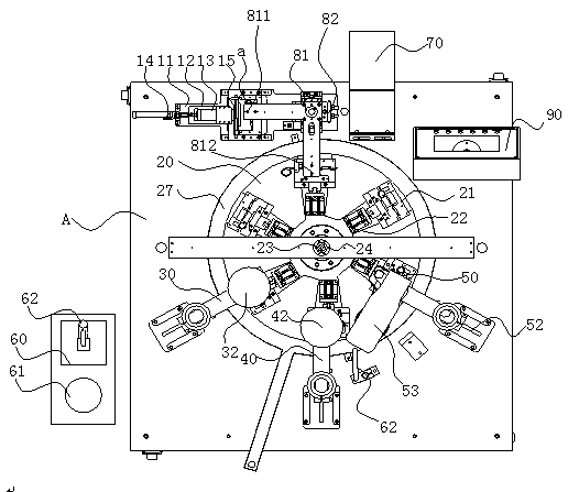
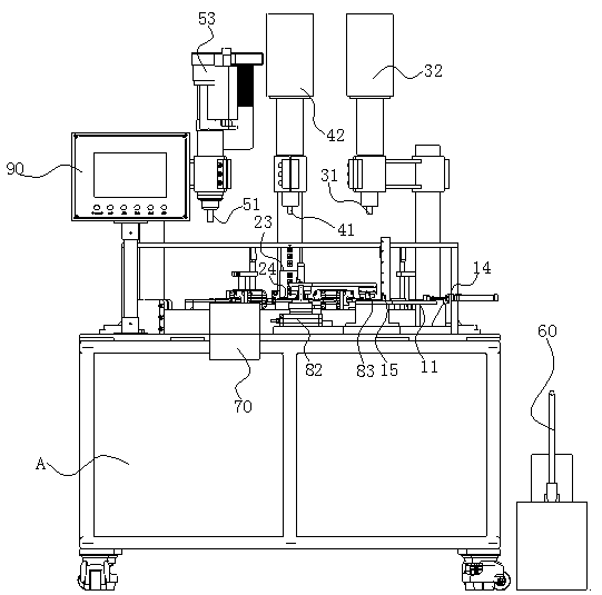
[0038] see Figure 1-2 As shown, a preferred embodiment of the present invention discloses a punching and tapping machine, comprising:

[0039] The feeding mechanism 10, the feeding mechanism 10 is used to transport the workpiece a to the feed end 811, the feeding mechanism 10 includes a feeding platform 11 arranged on an operation box cabinet A, and a loading platform fixed on the feeding platform 11 Horizontal track 12, the feed push plate 13 that is slidably connected with the horizontal track 12, the feed cylinder 14 that promotes the feed push plate 13 to translate along the horizontal track 12 and the clip-type charging box 15 that is located at the end of the horizontal track 12, the feed push The plate pushes the workpiece a in the clip-type charging box 15 to the fee...


PUM


Abstract

The invention provides a punching and tapping machine. The punching and tapping machine comprises a loading mechanism, a revolving table, a drilling station, a broaching station, a tapping station, acooling liquid supply system, a discharge pipe, an operation display panel, and a central control module for controlling the modules. The punching and tapping machine can realize full-automatic line production of loading, transmission, drilling, broaching and tapping, can finish machining of thread holes or polish holes through once clamping, and has the advantages of high production efficiency and high product precision.

Description

technical field [0001] The invention relates to an assembly line body, in particular to a punching and tapping machine. Background technique [0002] Scissors are daily necessities, which are divided into a moving blade part and a static blade part, and the two are rotatably connected together. Therefore, the scissors need to process threaded holes and light holes respectively on the movable blade portion and the static blade portion during production, and then the two are connected by threaded connectors. Thread processing generally needs to go through three processes of drilling, reaming and tapping, while processing light holes generally requires two processes of drilling and reaming. The existing production process separates the scissors on the equipment that can realize these processes. Processing requires multiple clamping. In this way, on the one hand, the processing accuracy of the threaded hole / light hole of each component is low, which is easy to cause large devi...

Claims


Application Information

Patent Timeline
Patent Type & Authority Applications(China)
IPC IPC(8): B23P23/02B23Q7/02B23Q11/00B23Q11/10
CPCB23P23/02B23Q7/02B23Q11/0053B23Q11/10
Inventor 赵龙清
Owner 顾宝洲
Why Eureka
Try Eureka