Eureka AIR delivers breakthrough ideas for toughest innovation challenges, trusted by R&D personnel around the world.

Chip recorder

Inactive Publication Date: 2007-01-25
HTC CORP
View PDF6 Cites 8 Cited by
  • Summary
  • Abstract
  • Description
  • Claims
  • Application Information

AI Technical Summary

Benefits of technology

[0007] In the embodiments of the invention, the first base and the second base can be selected to be mounted to the chip housing. The chip housing is detachably secured to the circuit board via a screw, and the upper portion and the lower portion of the base are mounted via a screw. Thus, by the invention, bases of different sizes can be selected to incorporate with the testing circuit boards for writing selected sizes of chips. Additionally, in the invention, the probe can be easily detached and replaced from the base.

Problems solved by technology

Thus, when a single clamp 14 is damaged, the whole chip recorder 1 and the test board T must be replaced, and manufacture cost is increased.

Method used


Image

  • Chip recorder
  • Chip recorder
  • Chip recorder

Examples


Embodiment Construction

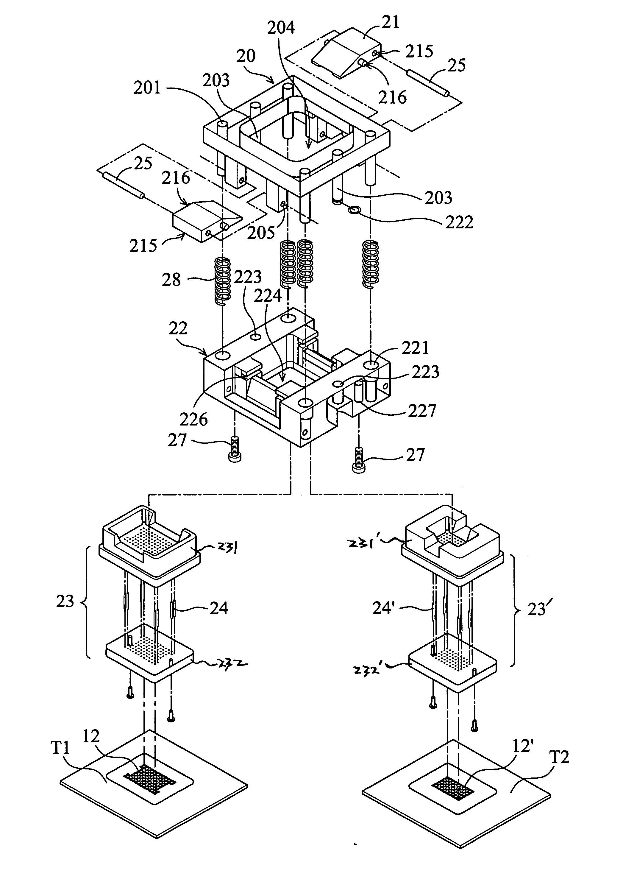
[0021]FIG. 2A depicts an exploded view of a chip recorder 2 of the invention. The chip recorder 2 comprises a bracket 20, two push fingers 21, a chip housing 22, and a first base 23. For different sizes of chips, the first base 23 can be replaced by a second base 23′ in use. The assembled chip recorder 2 is mounted on a testing circuit board T1 or a testing circuit board T2. When a chip C is placed into the chip recorder 2, testing circuit board T1 or the testing circuit board T2 writes or tests the chip C. Generally, four chip recorders 2 may be mounted on the testing circuit board T1 or on the testing circuit board T2, at the same time, for chip writing. The first base 23 comprises an upper portion 231 and a lower portion 232. The second base 23′ also comprises an upper 231′ and a lower portion 232′.

[0022] The first base 23 and the second base 23′ can be selected to mount to the chip housing 22 for different sizes of chips. When a first chip (for example, a chip with a diameter o...


PUM


Abstract

A chip recorder is disposed on a circuit board for writing a chip, wherein the chip comprises a contact and the circuit board comprises a contact. The chip recorder comprises a chip housing, a base, a bracket, a push finger and an elastic member. The chip housing is detachably secured on the circuit board for accommodating the chip. The base is detachably mounted to the chip housing and disposed between the chip housing and the circuit board wherein the base comprises at least one probe and a first end of the probe is electrically connected to the contact of the circuit board. The bracket is moveably connected to the chip housing and the push finger is pivotally connected to the bracket and moveably connected to the chip housing. The elastic member is disposed between the bracket and the chip housing to provide a resilient force against the bracket and the chip housing, wherein the resilient force allows the bracket and the push finger to move relative to the chip housing, and allows the push finger to abut against the chip to electrically connect a second end of the probe and the contact of the chip, and when the bracket is pressed toward the chip hosing, the push finger is moved to release the chip from the chip housing.

Description

BACKGROUND OF THE INVENTION [0001] 1. Field of the Invention [0002] The invention relates to a chip recorder, and in particular relates to a chip recorder of which the components are easily replaced. [0003] 2. Description of the Related Art [0004]FIG. 1A shows a conventional chip recorder 1 with a chip C installed therein. Tin balls (not shown) on the chip C contact the clamps 14 in the chip recorder 1. During chip writing, the chip recorder 1 is mounted on a testing circuit board T, and the clamps 14 electrically connect the chip C and allow the testing circuit board T to write the chip C. [0005]FIG. 1B is an enlarged view of portion A of FIG. 1A, which is a top view of the clamps 14. FIG. 1C is a side view of the clamps 14, in which the clamps 14 are V-shaped. FIGS. 1D and 1E show the clamps 14 clamping the tin balls C1 of the chip C. The clamps 14 are in a V-shaped configuration to clamp the tin balls of the chip for an electrical connection so that the clamps 14 are liable to be...

Claims


Application Information

Patent Timeline
IPC IPC(8): H01R13/62
CPCG01R1/0466
Inventor YANG, CHUN-WEILEI, SHIH-HUA
Owner HTC CORP
Why Eureka
Eureka Blog
Learn More