
Cleanroom workstation particle capture system

a technology of particle capture and workstation, which is applied in the field of system for the capture of particles, can solve the problems of dangerous blown off cycle of contaminants, insufficient system, and particle finding their way back onto the product, and achieve the effect of no blowback and high efficiency

Active Publication Date: 2020-04-07
SWAN JAWN P +2
View PDF33 Cites 5 Cited by
  • Summary
  • Abstract
  • Description
  • Claims
  • Application Information

AI Technical Summary

Problems solved by technology

In conventional cleanrooms, the particles can remain airborne in the workstation environment, presenting a danger that the particles can find their way back onto the products.
This presents a dangerous cycle of contaminants being blown off, sent airborne, and then returning.
This existing system may be adequate for some applications, but for critical components, such as implantable medical devices, these systems are inadequate and present certain disadvantages.
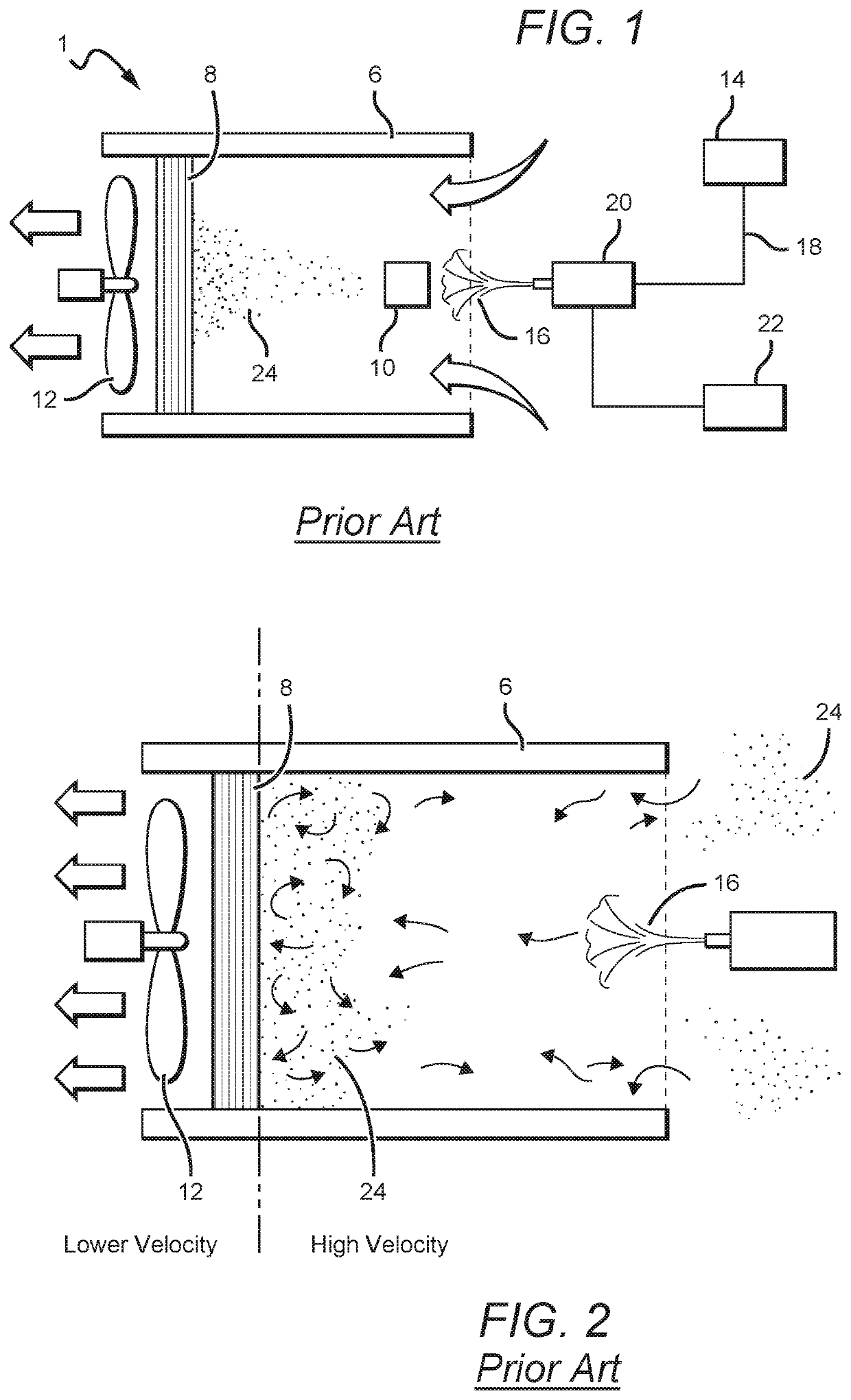
One primary disadvantage is that this system suffers from a phenomenon known as “blow back.” Referring now to FIG. 2, this blow back can occur when a particle 24 that has been blown off the work piece by the airstream 16 and is carried downstream toward the filter 8 by the negative pressure of the fan 12, is not captured by the filter 8.
This can cause significant losses in the indraft velocity pressure, which greatly reduces the ability of the indraft airstream to efficiently carry particulates to the filter 8 shown in FIGS. 1 and 2.
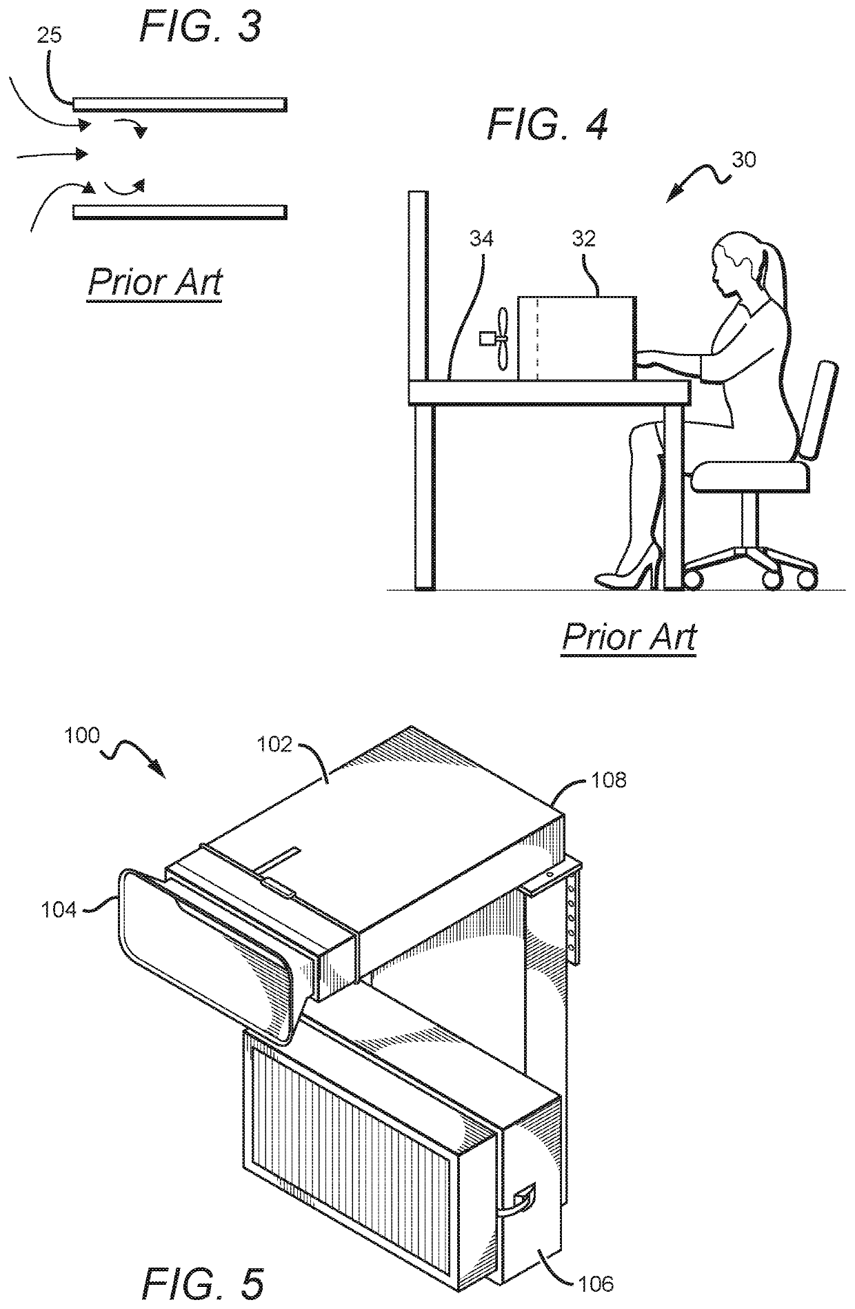
Another disadvantage of these conventional systems is that they are designed to reside on the bench top of a work station. FIG. 4 shows a cleanroom work station 30 with a conventional particle capture system 32 on the bench top 34.

Method used


Image

  • Cleanroom workstation particle capture system
  • Cleanroom workstation particle capture system
  • Cleanroom workstation particle capture system

Examples


Embodiment Construction

[0038]The present invention is directed to various embodiments of particle capture systems and also to workstations that utilize the particle capture systems. The systems can be used for many different applications, but are particularly applicable to cleanrooms and workstations for critical components or work pieces, such as implantable medical devices. For these critical components it is necessary to have an effective and reliable particle capture system for the removal of particles. The particles are typically blown off of the components and the particle capture systems according to the present invention efficiently capture the particles so that they are removed from the surrounding cleanroom environment and do not return to the component.

[0039]Particle capture systems according to the present invention can be arranged to convey and capture particulate debris at a filter. As described above, some embodiments comprise five major components including an ionized air gun, an inlet con...


PUM

PropertyMeasurementUnit
diameteraaaaaaaaaa
diameteraaaaaaaaaa
angleaaaaaaaaaa

Abstract

Cleanroom particle capture systems and cleanroom workstations include a duct carrying a particle capture air stream. A fan and a particle filter are arranged at the first end of the duct with at least some of the particle capture air stream passing through the filter, wherein the particle capture airstream has a first air velocity at the filter. A blow off device provides a blow off airstream into the duct at a second end of the duct, with the blow off airstream having a second air velocity at the second end that is higher than the first air velocity. The duct has one or more intervening features to reduce the second air velocity such that it substantially matches the first air velocity when the blow off airstream reaches the filter.

Description

[0001]This application claims the filing date and benefit of U.S. Provisional Patent Appl. Ser. No. 62 / 496,942, filed on Nov. 2, 2016.BACKGROUND OF THE INVENTIONField of the Invention[0002]This invention relates to systems for the capture of particles, and in particular to systems for the removal of particulate contaminants from parts or devices such as at a cleanroom workstation.Description of the Related Art[0003]When cleaning various substrates, parts or devices in a cleanroom, compressed air ionizing blow-off guns and nozzles can be used to neutralize surface static charges and blow off contaminants. In conventional cleanrooms, the particles can remain airborne in the workstation environment, presenting a danger that the particles can find their way back onto the products. This presents a dangerous cycle of contaminants being blown off, sent airborne, and then returning.[0004]A conventional system has been developed that is intended to capture a compressed air stream of blow off...

Claims


Application Information

Patent Timeline
Patent Type & Authority Patents(United States)
IPC IPC(8): B01D46/10B01D46/12B01D46/00A61L9/20
CPCB01D46/10B01D46/0043B01D2279/35B01D2279/51
Inventor SWAN, JAWN P.CARFARO, STEPHENSWAN, KEITH
Owner SWAN JAWN P
Learn More