Novel energy-saving environment-friendly numerical-control fume hood of laboratory

An energy saving, environmental protection, fume hood technology, applied in the direction of removing smoke and dust, cleaning methods and utensils, chemical instruments and methods, etc., can solve the problems of airflow vortex, gas overflow, and airflow disorder in the work area, so as to avoid energy waste, avoid The effect of exhaust gas overflow and uniform surface wind speed

Active Publication Date: 2013-09-04
GUANGZHOU SUIJIAN LAB TECH CO LTD +2
View PDF9 Cites 31 Cited by
  • Summary
  • Abstract
  • Description
  • Claims
  • Application Information

AI Technical Summary

Problems solved by technology

[0012] However, the deflector in the fume hood disclosed by the Chinese invention patent CN 1287914C belongs to a blind plate. When the gas flow entering the work area suddenly increases, for example, the ventilation When the movable sliding window in front of the cabinet is suddenly opened from the fully closed state (opening degree is zero) to increase the opening degree, at the moment of opening, it is easy to generate airflow vortex in the working area (at this time, the airflow on the upper part of the deflector suddenly increases. Large), the formed vortex will bring the harmful gas out of the fume hood through the opening of the sliding window, thus causing the gas to escape
[0013] In addition, the fume hoods currently used in laboratories are usually constant air volume fume hoods, that is, the exhaust air volume of each fume hood is fixed, but the actual During the test operation in the fume hood, different amounts of pollutant gases are often produced due to different tests
If a traditional constant air volume fume hood is used for exhaust treatment, the excessively high face velocity ...

Method used


Image

  • Novel energy-saving environment-friendly numerical-control fume hood of laboratory
  • Novel energy-saving environment-friendly numerical-control fume hood of laboratory
  • Novel energy-saving environment-friendly numerical-control fume hood of laboratory

Examples


Embodiment 1

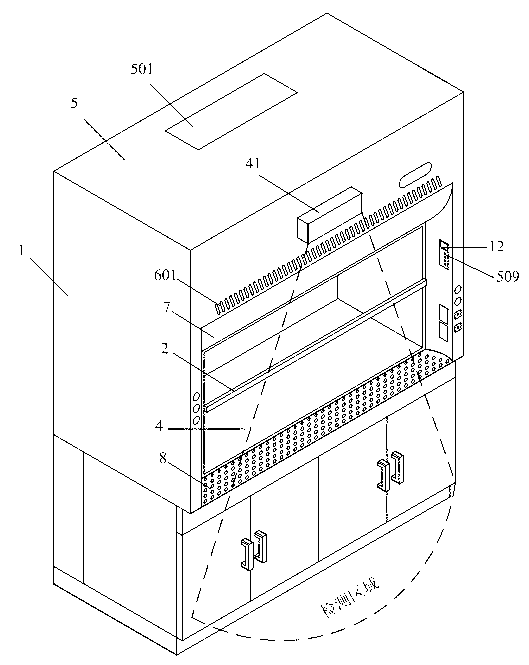
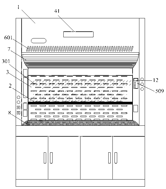
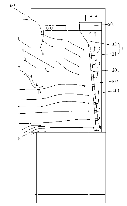
[0044] Embodiments of the present invention provide a novel energy-saving and environmental protection laboratory numerical control fume hood, such as Figure 1~3 As shown, it includes a cabinet body 1, a sliding window 2 and a deflector 3, and the sliding window 2 is arranged on the cabinet body to isolate the inside and outside of the cabinet body 1. The inner cavity 4 of the cabinet 1 constitutes the experimental work area (generally, the inner cavity of the cabinet 1 is provided with an experimental table). The deflector 3 is arranged in the inner cavity 4 of the cabinet 1 and is close to the inner wall 401 of the cabinet opposite to the sliding window 2, and an exhaust gas is formed between the deflector 3 and the inner wall 401 of the cabinet. Channel 402. The top 5 of the cabinet is provided with an air outlet 501 communicating with the exhaust channel 402, and the air outlet 501 is connected to an exhaust pipe to discharge the gas in the fume hood to the outside.

[...

Embodiment 2

[0054] refer to Figure 4 , the new energy-saving and environmental protection laboratory numerical control fume hood of the present embodiment, on the basis of embodiment 1, also comprises numerical control system 110, and described numerical control system 110 comprises sliding window automatic control device 111, non-contact sliding window control device 112, The surface wind speed control device 113 and the system control device 114, the sliding window automatic control device 110 is used to detect the presence / absence of an operator in the operating area in front of the fume hood and automatically control the increase / decrease of the opening of the sliding window. The non-contact sliding window control device 112 is used for the operator to open the sliding window to a desired position without contact. The face velocity control device 113 is used to automatically adjust the exhaust air volume of the fume hood according to the opening of the sliding window to maintain the ...

Embodiment 3

[0060] The embodiment of the present invention provides a surface wind speed adjustment device 113, such as Figure 5 As shown, the surface wind speed adjusting device comprises a displacement sensor 11 used to measure the opening of the sliding window of the fume hood, a controller 12 connected with the displacement sensor, and an exhaust air exhaust pipe 101 sequentially arranged on the fume hood. Fan 13 and variable air volume Venturi valve 15 , the air outlet of the variable air volume Venturi valve 16 is connected to the air inlet of the exhaust fan 13 , and the variable air volume Venturi valve 16 is connected to the controller 12 .

[0061] Specifically, combine figure 2 and Figure 4 , one end of the exhaust pipe 101 (ie Figure 5 A terminal in the fume hood) is connected to the exhaust outlet 51 of the fume hood, and the gas in the fume hood is discharged outside through the exhaust pipe 101 (ie Figure 4 in the B terminal). The gas in the fume hood enters the ex...


PUM


Abstract

The invention discloses a novel energy-saving environment-friendly numerical-control fume hood of a laboratory. The novel energy-saving environment-friendly numerical-control fume hood comprises a cabinet, a sliding window, a deflector and a numerical control system. The deflector is provided with a plurality of guide holes; air outside the fume hood flows into an inner cavity of the cabinet after the sliding window is opened; and under guiding of the deflector, gas generated in a testing area is exhausted from the guide holes of the deflector. The numerical control system comprises an automatic sliding window controller, a non-contact sliding window controller, a face velocity controller and a system controller. The automatic sliding window controller is used for detecting whether operators work in an operation area in front of the fume hood or not so as to automatically increase or decrease openness of the sliding window. The non-contact sliding window controller is used for the operators to open the sliding window to a required position in a non-contact way. The face velocity controller is used for regulating exhaust rate of the fume hood automatically according to the openness of the sliding window, and sending the exhaust rate and running states of the fume hood to the system controller so as to regulate running frequencies of an exhaust fan and an air supplement fan.

Description

technical field [0001] The invention relates to the technical field of laboratory equipment manufacturing, in particular to a novel energy-saving and environment-friendly laboratory numerical control fume hood. Background technique [0002] Laboratory ventilation is an integral part of laboratory design. In order to prevent laboratory workers from inhaling or inhaling some toxic, pathogenic or toxic chemicals and organisms, and to prevent the absorption of some vapors, gases and particles (smoke, soot, dust and aerosols), There should be good ventilation in the laboratory, and it can be removed by fume hood, fume hood or local ventilation. [0003] The most important function of the fume hood is the exhaust function. In the chemical laboratory, various harmful gases, odors, moisture, and flammable, explosive, and corrosive substances are produced during experimental operations. In order to protect the safety of users To prevent the pollutants in the experiment from spreadi...

Claims


Application Information

Patent Timeline
IPC IPC(8): B08B15/02
Inventor 易鸿
Owner GUANGZHOU SUIJIAN LAB TECH CO LTD
Why Eureka
Try Eureka