
Power conversion apparatus

a power conversion and power technology, applied in the direction of emergency power supply arrangements, process and machine control, instruments, etc., can solve the problems of complicated overall design of the power conversion apparatus, and achieve the effect of reducing the circuit layout area and overall design complexity

Active Publication Date: 2020-04-14
SPI ELECTRONICS
View PDF12 Cites 1 Cited by
  • Summary
  • Abstract
  • Description
  • Claims
  • Application Information

AI Technical Summary

Benefits of technology

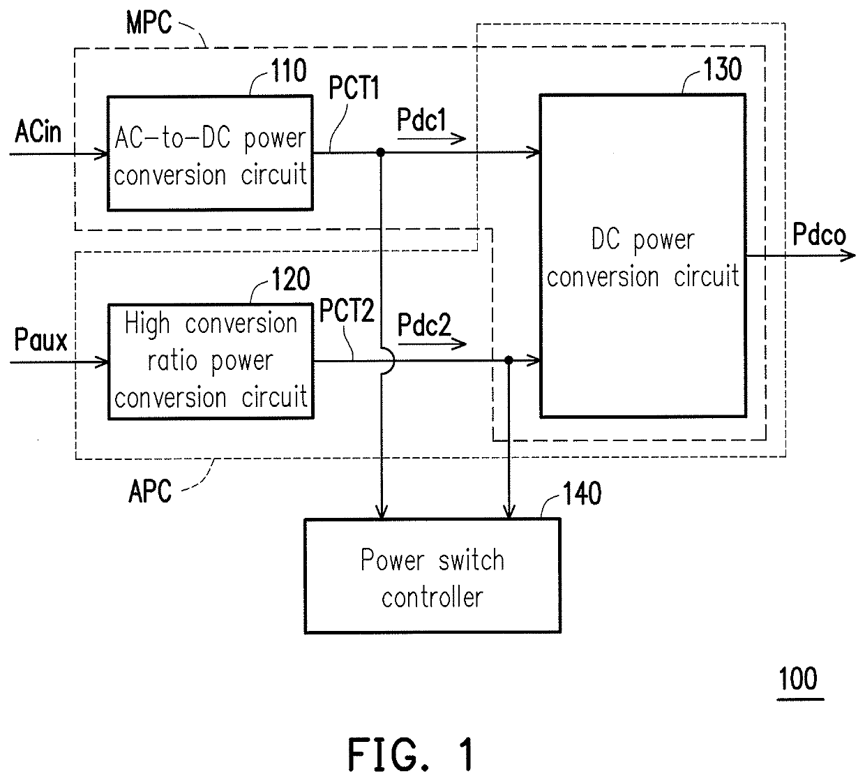
[0021]From the above, the power conversion apparatus of the invention generates an auxiliary DC power having a voltage value substantially identical to a main DC power via the high conversion ratio power conversion circuit, such that the main power converter and the auxiliary power converter can share a same back level DC power converter to generate a DC output voltage, and therefore, the overall design complexity and the circuit layout area of the power conversion apparatus are reduced.

Problems solved by technology

It is known that the current main-backup power conversion apparatus must require disposition of conversion circuits in the respective back level conversion circuits of the main power converter and the auxiliary power converter in order to perform power conversion, so both the main power converter and the auxiliary power converter cannot share one same DC power conversion circuit, and therefore, the overall design of the power conversion apparatus is more complicated.

Method used


Image

  • Power conversion apparatus
  • Power conversion apparatus
  • Power conversion apparatus

Examples


Embodiment Construction

[0027]Reference will now be made in detail to the present preferred embodiments of the invention, instances of which are illustrated in the accompanying drawings. Wherever possible, the same reference numbers are used in the drawings and the description to refer to the same or like parts.

[0028]FIG. 1 is a schematic diagram illustrating a power conversion apparatus 100 according to an exemplary embodiment. Referring to FIG. 1, the power conversion apparatus 100 includes an AC-to-DC power conversion circuit 110, a high conversion ratio power conversion circuit 120, a DC power conversion circuit 130, and a power switch controller 140. In this exemplary embodiment, the power conversion apparatus 100 is adapted to supply power to electronic devices such as tablet PC, pocket PC, personal computers, laptops, personal digital assistants (PDAs), smart phones, but not limited thereto.

[0029]The AC-to-DC power conversion circuit 110 receives an external AC power ACin (as an instance but not lim...


PUM


Abstract

A power conversion apparatus including a main power converter and an auxiliary power converter is provided. The main power converter converts an AC power to a first DC power, and then converts the first DC power to a DC output power. The main power converter has a first power conversion terminal for outputting the first DC power. The auxiliary power converter converts an auxiliary power to a second DC power, and then converts the second DC power to the DC output power. The auxiliary power converter has a second power conversion terminal for outputting the second DC power. The first power conversion terminal and the second power conversion terminal are commonly coupled to a DC power conversion circuit, such that the main power converter and the auxiliary power converter share the DC power conversion circuit and generate a DC output power.

Description

CROSS-REFERENCE TO RELATED APPLICATION[0001]This application claims the priority benefit of Taiwan application serial no. 104122513, filed on Jul. 13, 2015. The entirety of the above-mentioned patent application is hereby incorporated by reference herein and made a part of this specification.BACKGROUND OF THE INVENTIONField of the Invention[0002]The invention relates to a power conversion apparatus, and more particularly, to a power conversion apparatus having a power supply structure with a main power converter and an auxiliary power converter.Description of Related Art[0003]As internet and technology rapidly develop, the demands of enterprises for information technology (IT) are also increasing. As a result, integrated computers having high speed computing and large storage capabilities are formed by integrating a large number of servers through the internet, and are widely adopted by enterprises. In addition, many electronic devices are dedicated to processing and computing impor...

Claims


Application Information

Patent Timeline
Patent Type & Authority Patents(United States)
IPC IPC(8): H02J5/00H02M3/156H02M1/10H02M1/00
CPCH02M3/156H02M1/10H02J5/00H02M2001/007H02J9/061H02J9/068H02J2207/40H02M1/007
Inventor TSAI, CHIEN-LI
Owner SPI ELECTRONICS
Learn More