Transfer Case for a Motor Vehicle Powertrain

a technology for motor vehicles and powertrains, applied in mechanical devices, gearing details, transportation and packaging, etc., can solve the problems of long duration and high speed wheel slip events, continual drag on powertrain components, and interference with brake traction control, so as to reduce the drag and fuel efficiency of the driveline, reduce unnecessary noise, and reduce the effect of the clutch

Inactive Publication Date: 2009-06-04
FORD GLOBAL TECH LLC
View PDF17 Cites 19 Cited by
  • Summary
  • Abstract
  • Description
  • Claims
  • Application Information

AI Technical Summary

Benefits of technology

[0012]It is an advantage of this invention that the driveline drag and fuel efficiency reduction associated with viscous shear continually present in a transfer case having at least one disengaged, hydraulically actuated range clutch is eliminated.
[0013]It is another advantage that unnecessary noise caused by continual rotation of the transfer case and driveline components unintentionally driven by a disengaged hydraulic clutch is eliminated.
[0014]It is yet another advantage that the space normally required to package a low range clutch and high range clutch in a transfer case is avoided. The design, manufacturing and assembly complexity and cost required to supply these clutches with hydraulic fluid and the control system features that synchronize their engagements and disengagements is eliminated.

Problems solved by technology

Length periods to engage the clutch can result in long duration and high speed wheel slip events before the clutch engages and torque is sent to the non-slipping wheels.
Also long disengagement periods can interfere with brake traction control.
This action produces a continual drag on the powertrain components, increasing fuel consumption and adding to noise and noise amplification in the driveline.
Its size presents packaging difficulties in the transfer case where two other clutches, an epicyclic train and a drive mechanism to the front wheels are also located.

Method used


Image

  • Transfer Case for a Motor Vehicle Powertrain
  • Transfer Case for a Motor Vehicle Powertrain
  • Transfer Case for a Motor Vehicle Powertrain

Examples


Embodiment Construction

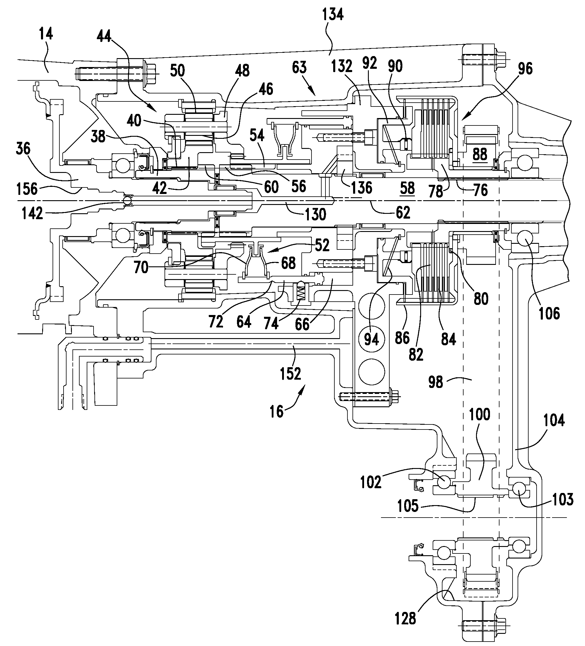
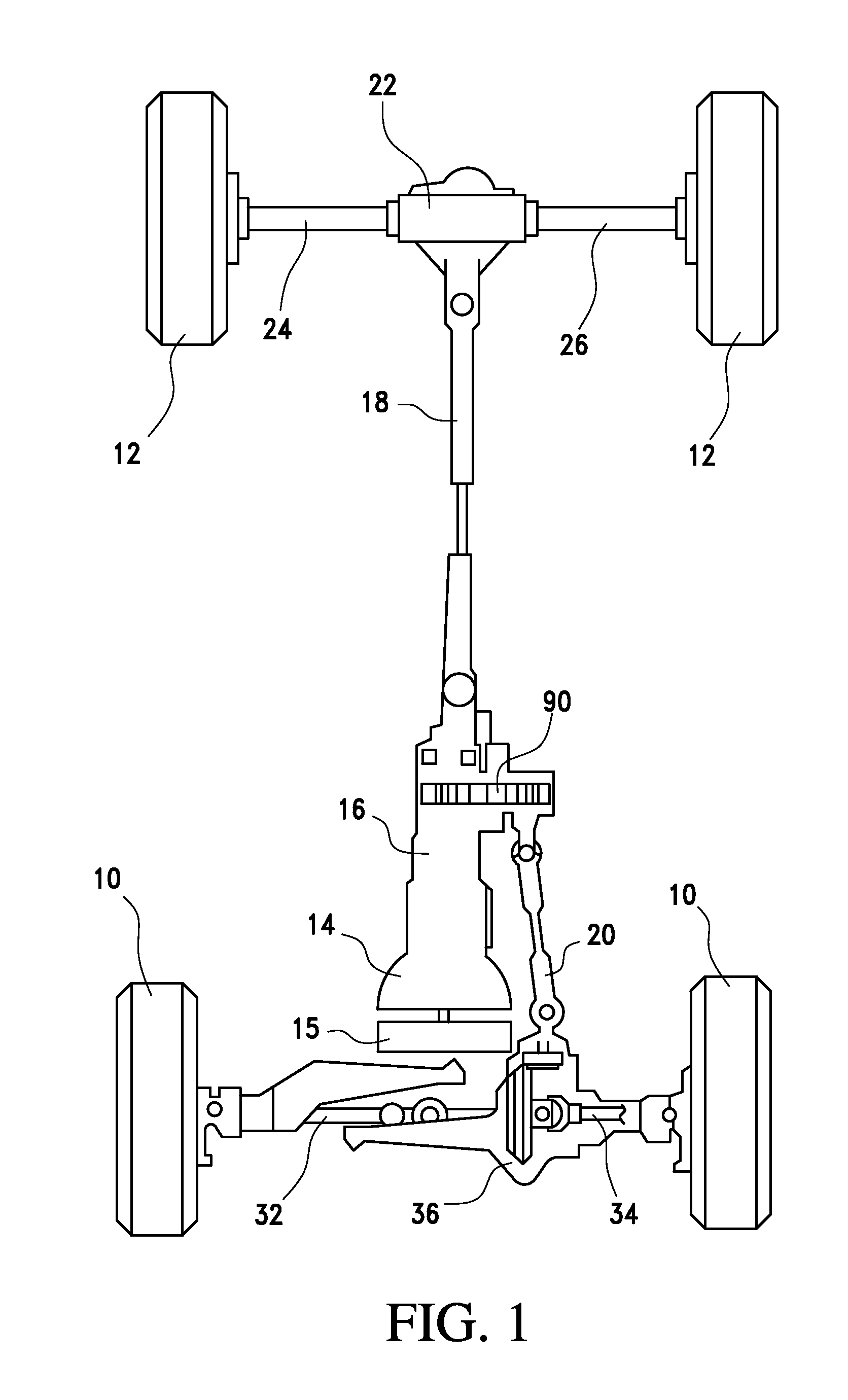
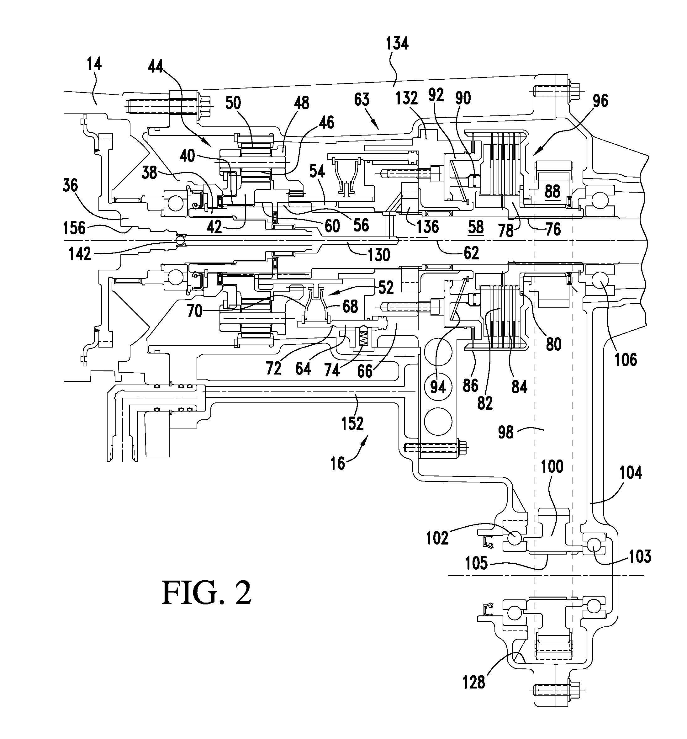
[0020]Referring now to the drawings, there is illustrated in FIG. 1 a powertrain for a motor vehicle, to which the present invention can be applied. The powertrain includes front and rear wheels 10, 12, a power transmission 14 for producing multiple forward and reverse speed ratios driven by an engine 15, and a transfer case 16 for continuously driveably connecting the transmission output to a rear drive shaft 18. The transfer case 16 continually connects the transmission output to the rear drive shaft 18, and selectively connects the transmission output to the front drive shaft 20 when a four wheel drive mode of operation is selected, either manually or electronically. Shaft 18 transmits power to a rear wheel differential mechanism 22, from which power is transmitted differentially to the rear wheels 12 through axle shafts 24, 26, which are contained within a differential housing. The front wheels are driveably connected to right-hand and left-hand half shafts 32, 34, to which powe...


PUM


Abstract

A motor vehicle powertrain includes a multiple speed transmission including a first lube circuit that supplies hydraulic lubricant to components of the transmission, a first oil sump, and a first pump driveably connected to an engine for supplying oil at a first pressure to the lube circuit, a transfer case including a first output, a second oil sump located in the transfer case, a second pump located in the transfer case and driveably connected to the first output, and a check valve for alternately opening and closing a connection between the first pump and the lube circuit and for opening and closing a connection between the second pump and the lube circuit in response to differential pressure between an outlet of the first pump and an outlet of the second pump.

Description

BACKGROUND OF THE INVENTION[0001]1. Field of the Invention[0002]This invention relates generally to a driveline for a motor vehicle, and in particular, to a driveline having a transfer case for directing power to front wheels and rear wheels.[0003]2. Description of the Prior Art[0004]A transfer case may include a planetary gear set for producing either a “high” range, in which the transfer case output is driven at the same speed as the input, or a “low” range, in which the output is driven slower than its input speed. The 4×2 (High), 4×4 (High) and 4×4 Low states of the transfer case are usually selected manually by the vehicle operator by operating a lever or switch. A first position of the lever will cause a range selection device in the transfer case to direct power from the transmission output to a rear drive axle, the 4×2 drive mode. A second position of the lever will cause the transfer case to direct power to both a front drive axle and a rear drive axle, the 4×4 drive mode. ...

Claims


Application Information

Patent Timeline
Patent Type & Authority Applications(United States)
IPC IPC(8): F16H57/08F16H57/04
CPCF16H57/0409F16H57/0483F16H57/0434B60R17/00F01M1/16F01M1/20F16H57/0447
Inventor THOMAS, STEVEN G.PERAKES, ANDREAS E.HAMMOND, MATTHEW D.FRAIT, STEVEN A.DEGRAFFENREID, MONICA R.GOLESKI, GREGORY D.HARTINGER, CHIPMAURER, JEFFREY E.
Owner FORD GLOBAL TECH LLC
Why Eureka
Try Eureka