Supercharge Your Innovation With Domain-Expert AI Agents!

Rare earth permanent magnet and rare earth permanent magnet manufacturing method

a technology manufacturing methods, which is applied in the field of can solve the problems of insufficient exchange interaction, inability to obtain desired nanocomposite structures, and ineffective enhancement of magnetic properties of the above-described nanocomposite rare earth permanent magnets, and achieve the effect of enhancing the magnetic momen

Active Publication Date: 2020-04-21
IHI CORP
View PDF33 Cites 0 Cited by
  • Summary
  • Abstract
  • Description
  • Claims
  • Application Information

AI Technical Summary

Benefits of technology

The patent text describes a way to increase the magnetic strength of rare earth magnets by using a specific compound with a crystal structure. This results in stronger coercive force, increased magnetic flux density, and higher energy product.

Problems solved by technology

So, there is a possibility that a sufficient exchange interaction may not be obtained.
Furthermore, if reducing power is weak, alloy nanoparticles tend to easily become just an aggregate of single-layer nanoparticles and a desired nanocomposite structure cannot be obtained.
Therefore, it is presumed that the magnetic property of the above-described nanocomposite rare earth permanent magnet may not be enhanced effectively.
However, a coercive force Hcj of the relevant Nd2Fe14B particles manufactured at a high temperature is not good.

Method used


Image

  • Rare earth permanent magnet and rare earth permanent magnet manufacturing method
  • Rare earth permanent magnet and rare earth permanent magnet manufacturing method
  • Rare earth permanent magnet and rare earth permanent magnet manufacturing method

Examples


examples

[0178]The present disclosure will be further explained by referring to examples below. However, the present disclosure is not limited to the examples described below.

examples 1 to 5

[0179]Cobalt (Co), Nd, Fe, and B were arc-melted, thereby obtained a raw material alloy. The obtained 5 kg alloy was coarsely ground with the ball mill, thereby obtaining alloy particles with an average particle diameter of 16 μm. Subsequently, the alloy particles was dispersed in a solvent. An additive was introduced into the dispersed solution, which was then stirred to cause a reduction reaction to refine the alloy particles. An average particle diameter of the obtained fine alloy powder was 16 to 25 μm. The same process can be conducted on any one type of metal from among beryllium (Be), lithium (Li), aluminum (Al), and silicon (Si) besides cobalt (Co).

[0180]Respective samples of the above-described fine alloy powder were used as raw material compounds 1 to 5 and their magnetic moments were calculated by referring to atomic locations obtained by a neutron diffraction method (O. Isnard et. al J. Appl. Phys. 78 (1995) 1892-1898). Table 2 shows the magnetic moments of the raw mater...

example 6 to example 14

[0183]The raw material alloy containing the respective elements with the content indicated in FIG. 7 was ground, thereby obtaining alloy particles. Subsequently, the alloy particles were dispersed in a solvent. An additive was introduced to the dispersed solution, which was then stirred to cause a reduction reaction, thereby refining the alloy particles. An average particle diameter of the alloy particulates of Example 6 and Example 9 was 16 to 25 μm. The average particle diameter (powder particle size) of the alloy particulates of Example 7, Example 8, and Example 10 to Example 12 was 3 to 11 μm. The average particle diameter was measured with an apparatus equivalent to a laser-diffraction-type particle-size distribution measuring apparatus SALD-2300 made by SHIMADZU CORPORATION.

[0184]The molding cavity was filled with 500 g of the obtained alloy particulates 500 g and a 19 kOe magnetic field with a molding pressure of 2 t / cm2 was applied to the alloy particulates of each example t...


PUM

PropertyMeasurementUnit
particle size D50aaaaaaaaaa
densityaaaaaaaaaa
temperatureaaaaaaaaaa

Abstract

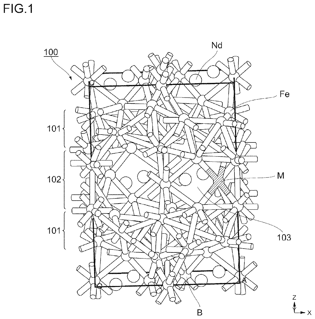
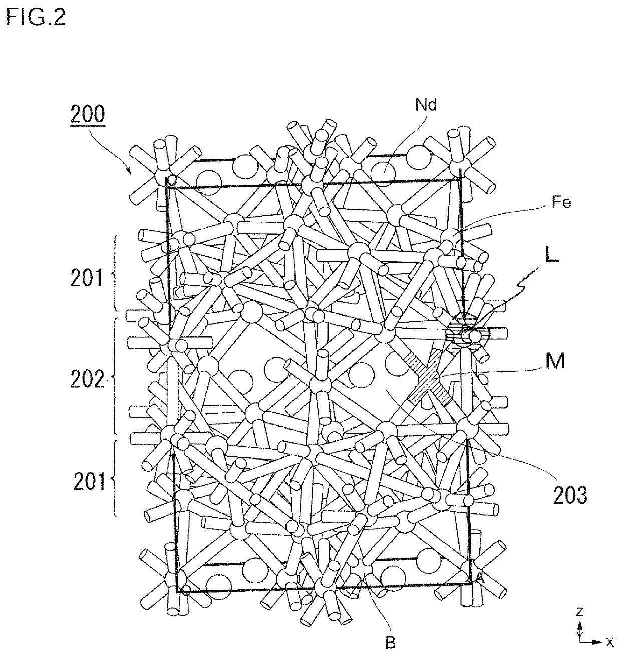
A magnetic property of a rare earth permanent magnet containing neodymium, iron, and boron is enhanced. The present disclosure is a rare earth permanent magnet with a compound represented by a following expression as a main phase: Nd2Fe14B(1-x)Mx. In the expression, M represents an element selected from any one of cobalt, beryllium, lithium, aluminum, and silicon and x satisfies 0.01≤x≤0.25. The main phase has an Nd—Fe—B layer and an Fe layer periodically and part of boron is substituted with any one or more types of elements selected from a group consisting of cobalt, beryllium, lithium, aluminum, and silicon.

Description

TECHNICAL FIELD[0001]The present disclosure relates to a rare earth permanent magnet containing neodymium, iron, and boron.BACKGROUND ART[0002]As a technique to enhance a magnet property of a rare earth permanent magnet containing neodymium (Nd), iron (Fe), and boron (B), there is a magnet in which Fe is substituted with Co (PTL 1). PTL 1 describes that a coercive force Hc, residual magnetic flux density Br, maximum energy product BHmax, and so on of permanent magnets in which Fe is substituted with other atoms were measured exhaustively, thereby showing enhancement of the magnetic property of the above-described permanent magnet.[0003]Furthermore, PTL 2 discloses a rare earth sintered magnet that contains, by percent by weight: R (where R is at least one type of rare earth elements including Y and Nd accounts for 50 atom % or more of R): 25 to 35%; B: 0.8 to 1.5%; M (at least one type selected from Ti, Cr, Ga, Mn, Co, Ni, Cu, Zn, Nb, and Al) when necessary: 8% or less; and the rema...

Claims


Application Information

Patent Timeline
Patent Type & Authority Patents(United States)
IPC IPC(8): H01F1/057C22C38/16C22C38/14C22C38/12C22C38/10C22C38/06C21D6/00C21D9/00C22C33/02H01F41/02C22C38/00B22F3/00
CPCH01F1/057B22F3/00C22C38/002C22C38/005C22C38/16C21D9/0068C22C38/06H01F1/0577C21D6/007C22C38/14C22C38/12H01F41/0253C22C38/00C22C38/10H01F41/0273C22C33/0278C22C2202/02B22F2999/00B22F9/20B22F3/02B22F9/04B22F2201/20B22F2998/10B22F3/10B22F2202/05
Inventor EGUCHI, HARUKINAKANOWATARI, ISAOYONEYAMA, NATSUKITOMONO, HIDEKAZUTAKAHASHI, HIROO
Owner IHI CORP
Features
  • R&D
  • Intellectual Property
  • Life Sciences
  • Materials
  • Tech Scout
  • Unparalleled Data Quality
  • Higher Quality Content
  • 60% Fewer Hallucinations
Learn More