Disposable eye patch/shield

a technology of eye patch and shield, which is applied in the field of eye patch/shield, can solve the problems of eye patch not being comfortable to wear, liquid or medicine, and requiring very delicate and detailed work

Active Publication Date: 2020-04-28
OCULO PLASTIK
View PDF22 Cites 1 Cited by
  • Summary
  • Abstract
  • Description
  • Claims
  • Application Information

AI Technical Summary

Benefits of technology

[0011]The eye shields of the invention are made using an outer layer of a flat or formed, semi-flexible or rigid metal foil that extends all the way to the edge of the shield, including the adhesive area of the shield that adheres to the patient. The foil layer may be combined with one or more layers of polyester foam to avoid reflection to the user or to provide for heat insulation, adhesion and patient comfort. The shield is flat or curved to the extent necessary at the contact portion to fit over the orbital area of the patient's eye. A release layer covering the adhesive is open to allow for stacking of the curved versions of the shields until ready for use.

Problems solved by technology

In performing surgical or other procedures to such areas of the faces, the procedures often require very delicate and detailed work, and therefore doctors and other professionals must have access to as much unobstructed area as possible.
However, since the tabs do not seal the entire edge of the eye patch around the eye, there is a possibility that liquids or medicines may enter a patient's eye covered by this eye patch.
However, since this patch is adhered onto the patient's eyelid as well as surrounding eye tissues, this eye patch is not comfortable to wear, and this is the only option for this patch.
Because of its large size, this patch is not suitable for many surgical and facial care procedures which require a larger working area for the surgeon.
However, because of the adhesive areas in the center part, it is uncomfortable for the patient to wear, and, in fact, it is designed for use on an anesthetized patient.
However, this patch is quite large, being designed to attach to the outside of the eye socket, and covers some areas of the face that may need to be accessed for some surgical or facial care procedures.

Method used


Image

  • Disposable eye patch/shield
  • Disposable eye patch/shield
  • Disposable eye patch/shield

Examples


Embodiment Construction

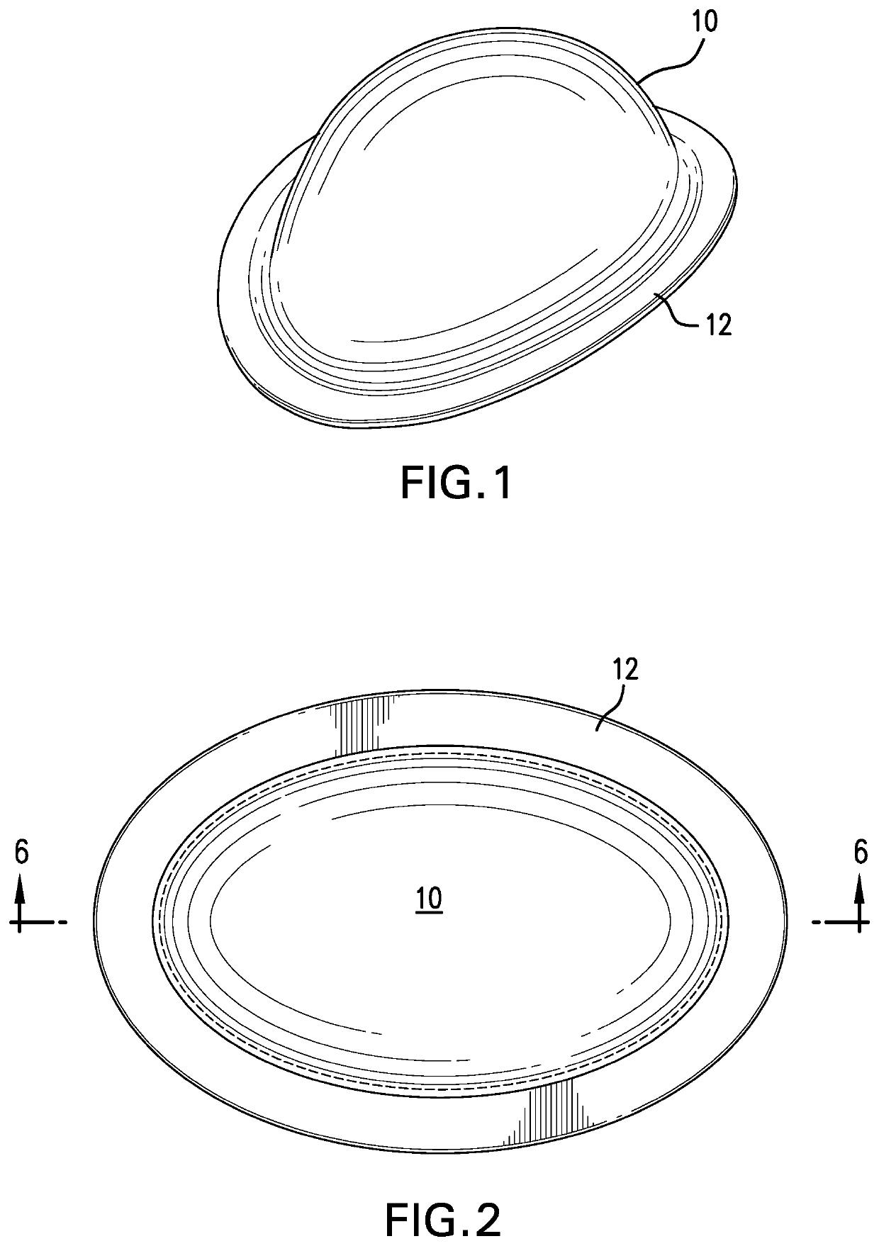
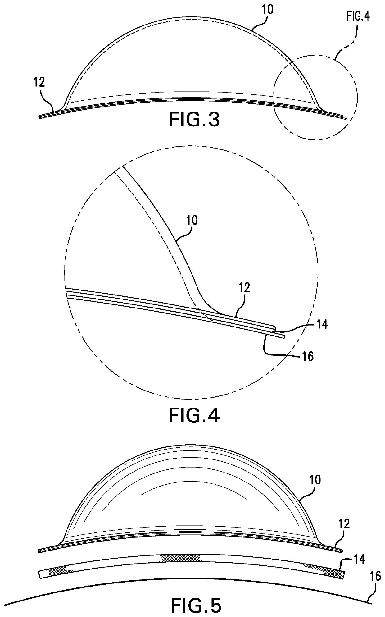
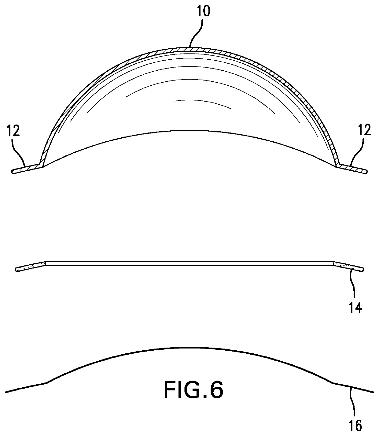
[0023]Referring to FIGS. 1-6 of the drawings, the basic structure of the eye shield of the invention is a semi-flexible or rigid shell 10, preferably made from a material of some metal, such as aluminum. The shell 10 can be pure metal or metal coated with some suitable material, such as polyester or foam, but not limited to polyester or foam, on top or on both sides, as shown in the various embodiments described herein. This is so the shield can be used when shielding both a light energy beam and electrical currents. Some energy skin treatment units on the market come both with an electrical current (radio frequency (RF), and a light energy, like laser, IPL, etc. Ideally, the shell 10 will protect against units with electrical currents, such as RF, but will also protect against energies in addition to RF. The shell 10 must also withstand some energy exposure from a light beam source, such as a laser beam to be safely used as a shield. The metallic shell 10 is formed in any suitable ...


PUM


Abstract

A shield for protecting the eye of a patient who is undergoing treatment of a facial area, such as the nose-bridge, forehead, temple, or an area immediately surrounding the eye. The shield has an outer shell of a formed semi-flexible or rigid metal foil that extends all the way to the edge of the shield, including an adhesive area of the shield that holds the shield around the eye of the patient. The foil layer is combined with one or more layers of polyester to avoid reflection of the light energy on the user or one or more layers of foam to provide for heat insulation, adhesion and patient comfort. The shield is formed at the contact portion to fit over the orbital area of the patient's eye.

Description

[0001]This application claims priority under 35 USC 119 to Provisional Patent Application No. 62 / 198,743 filed on Jul. 30, 2015 the contents of which are hereby incorporated by reference.FIELD OF THE INVENTION[0002]This invention relates to a disposable eye patch / shield. In particular, this invention relates to a disposable eye patch / shield used during surgical and / or professional facial care procedures.BACKGROUND OF THE INVENTION[0003]Cosmetic surgical procedures (e.g., plastic surgery) and professional facial care procedures are becoming increasingly popular. In some cases, patients request such procedures for treatments to such facial areas as the nose-bridge, forehead, temples, and areas immediately surrounding the eyes. In performing surgical or other procedures to such areas of the faces, the procedures often require very delicate and detailed work, and therefore doctors and other professionals must have access to as much unobstructed area as possible. At the same time, the do...

Claims


Application Information

Patent Timeline
Patent Type & Authority Patents(United States)
IPC IPC(8): A61F9/04A61B90/00
CPCA61F9/04A61B90/04A61F2250/0047A61F2220/0008A61B2090/049A61B2090/0454A61B2090/0481
Inventor DURETTE, JEAN-FRANCOIS
Owner OCULO PLASTIK
Why Eureka
Try Eureka