Hinge for the rotatable movement of a door, a shutter or the like

a technology of hinges and doors, applied in the direction of pin hinges, door/window fittings, wing accessories, etc., to achieve the effect of high functionality

Active Publication Date: 2020-04-28
COLCOM GRP SPA
View PDF23 Cites 4 Cited by
  • Summary
  • Abstract
  • Description
  • Claims
  • Application Information

AI Technical Summary

Benefits of technology

[0005]Object of the present invention is to at least partially overcome the above drawbacks, by providing a hinge having features of high functionality and cost-effectiveness.
[0008]Another object of the invention is to provide a hinge extremely easy to install.
[0009]Another object of the invention is to provide a hinge extremely easy to mount.

Problems solved by technology

Said hinges are susceptible to improvements, in particular for what concerns the cost and the simplicity in mounting thereof.

Method used


Image

  • Hinge for the rotatable movement of a door, a shutter or the like
  • Hinge for the rotatable movement of a door, a shutter or the like
  • Hinge for the rotatable movement of a door, a shutter or the like

Examples


Embodiment Construction

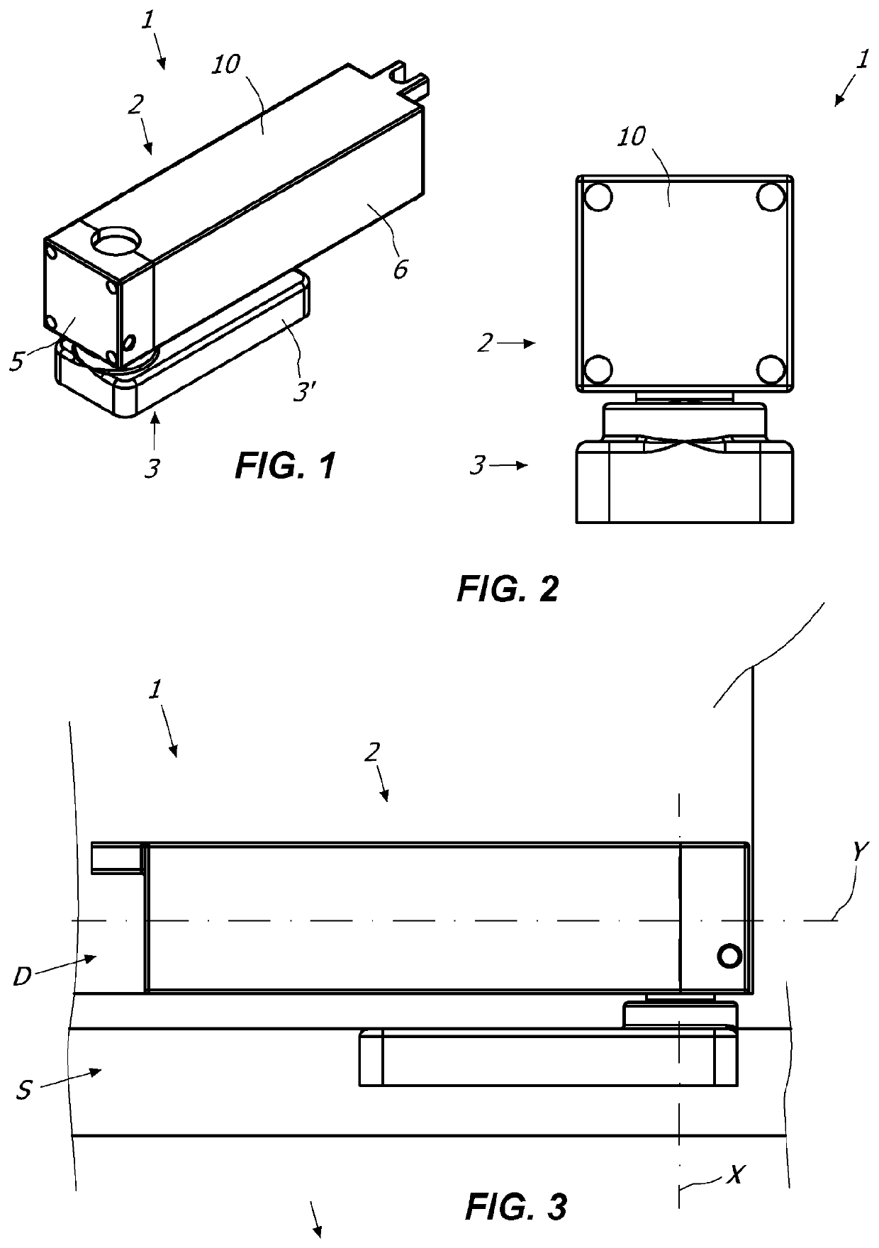
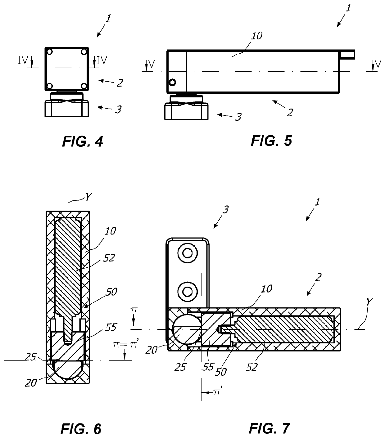
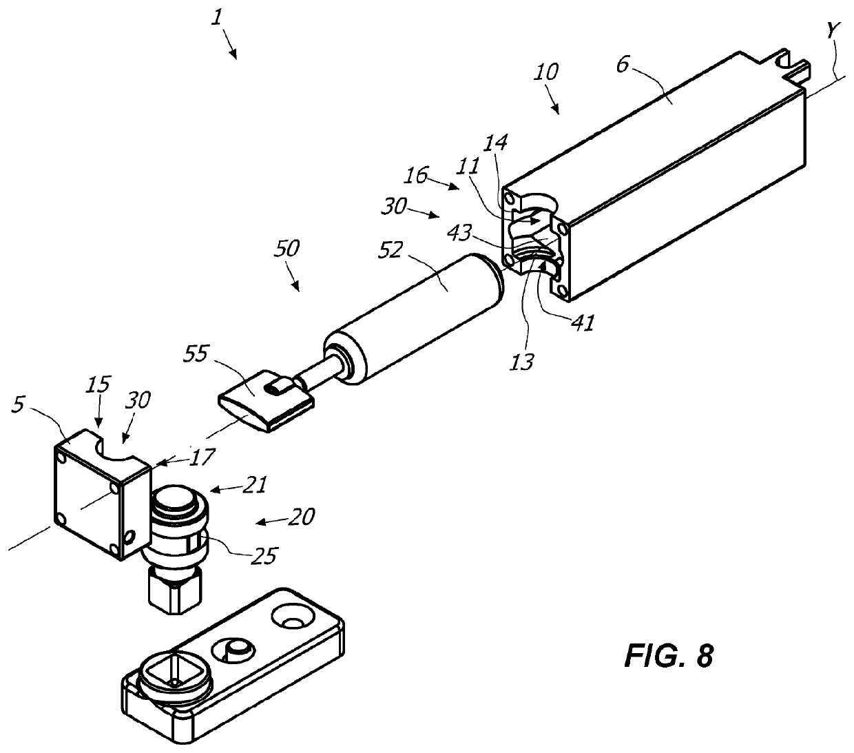
[0037]Referring to the mentioned drawings, it is described a hinge 1 particularly useful for the rotatable movement and / or control of at least one closing element D, such as a door, a shutter, a gate or the like, which is anchorable to a stationary support structure S, such as a wall and / or a frame of a door or of a window and / or a support pillar and / or the floor.

[0038]In particular, the closing element D may rotate between at least one closed position and at least one open position.

[0039]It is understood that depending on the configuration, the hinge 1 may allow the automatic opening and / or closing of the closing element D and / or the control during the opening and / or closing of the closing element D itself.

[0040]The hinge 1 may then comprise one elongated fixed element 2 defining an axis Y anchorable to one between the stationary support structure S and the closing element D and at least one movable element 3 defining an axis X anchorable to the other between the stationary support...


PUM

PropertyMeasurementUnit
anti-frictionaaaaaaaaaa
rotatable movementaaaaaaaaaa
dimensionsaaaaaaaaaa

Abstract

A hinge for the rotatable movement of a closing element, such as a door, a window, a shutter or the like, between a closing position and an opening position, the closing element being anchorable to a stationary support structure, such as a wall, a floor, a frame or similar, includes a hinge body anchorable to the stationary support structure or the closing element, and a pivot defining an axis and anchorable to the closing element or the stationary support structure. The pivot and the hinge body are coupled so as to cause the closing element to rotate between the opening and the closing position. The hinge body includes a working chamber defined along the axis to house the pivot.

Description

FIELD OF THE INVENTION[0001]The present invention is generally applicable in the technical field of the control or closing hinges, and it relates in particular to a hinge for the rotatable movement of a door, a shutter or the like.BACKGROUND OF THE INVENTION[0002]Hinges comprising a box-shaped hinge body and a pivot each other reciprocally coupled in order to allow a closing element, such as a door, a shutter or the like, to rotate between an open position and a closed position.[0003]Said known hinges include also a working chamber within the box-shaped hinge body which houses the pivot.[0004]Said hinges are susceptible to improvements, in particular for what concerns the cost and the simplicity in mounting thereof.SUMMARY OF THE INVENTION[0005]Object of the present invention is to at least partially overcome the above drawbacks, by providing a hinge having features of high functionality and cost-effectiveness.[0006]Another object of the invention is to provide a hinge of compact di...

Claims


Application Information

Patent Timeline
Patent Type & Authority Patents(United States)
IPC IPC(8): E05F3/22E05D11/00E05D11/02E05D5/14E05D9/00E05D5/10E05D3/02E05F3/04
CPCE05F3/04E05D5/10E05D11/02E05D5/14E05D3/02E05D11/0054E05D9/005E05Y2201/212E05Y2900/132E05Y2900/146E05Y2800/676E05Y2900/148E05D11/1014E05D11/105E05Y2201/10E05Y2201/638
Inventor BENEDETTI, LUCAMESAROS, MIHAI
Owner COLCOM GRP SPA
Why Eureka
Try Eureka