
EGR device

a technology of egr and device, which is applied in the direction of electric control, machines/engines, combustion engines, etc., can solve problems such as troublesome egr systems

Active Publication Date: 2020-04-28
YANMAR POWER TECHNOLOGY CO LTD
View PDF38 Cites 0 Cited by
  • Summary
  • Abstract
  • Description
  • Claims
  • Application Information

AI Technical Summary

Benefits of technology

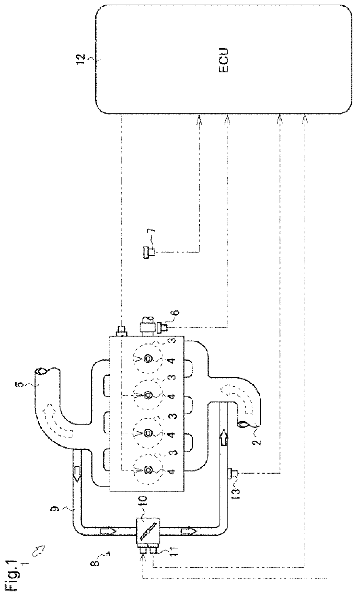
The present invention relates to a system for controlling an engine's exhaust gas recirculation (EGR) valve based on the engine's rotation speed and fuel injection rate. The system can determine if the engine is idling or under high load and control the EGR valve accordingly. This allows for efficient control of the engine's EGR valve regardless of the accelerator's operation state, resulting in improved engine performance. Additionally, the system can reliably recognize the engine's operation state even at near thresholds, ensuring accurate control of the EGR valve. The system can also adapt its operation based on the engine's usage, making it more efficient and effective.

Problems solved by technology

In such an engine, when the exhaust gas is refluxed for a long time in an idling operation state in which the exhaust gas contains unburned fuel, this unburned fuel adheres to the EGR device, potentially causing trouble to the EGR system.

Method used


Image

  • EGR device
  • EGR device
  • EGR device

Examples


first embodiment

[0106]According to the EGR valve control, which is illustrated in FIG. 6B, the ECU 12 closes the EGR valve 10 at a maximum closing speed at operation time T2. Then, the ECU 12 opens the EGR valve 10 at a maximum opening speed at operation time T3. In other words, if the operation state of the engine 1 no longer satisfies the idling operation condition, the ECU 12 immediately opens the EGR valve 10.

second embodiment

[0107]According to the EGR valve control, which is illustrated in FIG. 6C, the ECU 12 closes the EGR valve 10 at the maximum closing speed at operation time T2. Then, the ECU 12 opens the EGR valve 10 at the maximum opening speed at operation time T4. In other words, if the operation state of the engine 1 no longer satisfies the idling operation condition, the ECU 12 opens the EGR valve 10 immediately after a count-down time that can be optionally set has passed.

third embodiment

[0108]According to the EGR valve control, which is illustrated in FIG. 6D, the ECU 12 closes the EGR valve 10 at the maximum closing speed at operation time T2. Then, the ECU 12 starts opening the EGR valve 10 at an opening speed that is optionally set at operation time T3. In other words, if the operation state of the engine 1 no longer satisfies the idling operation condition, the ECU 12 opens the EGR valve 10 in an optional time.


PUM


Abstract

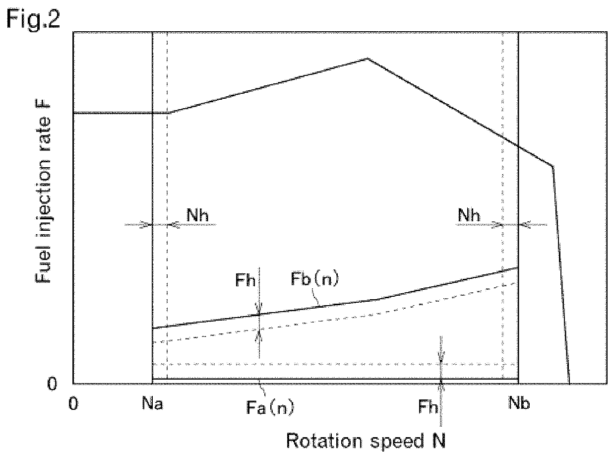
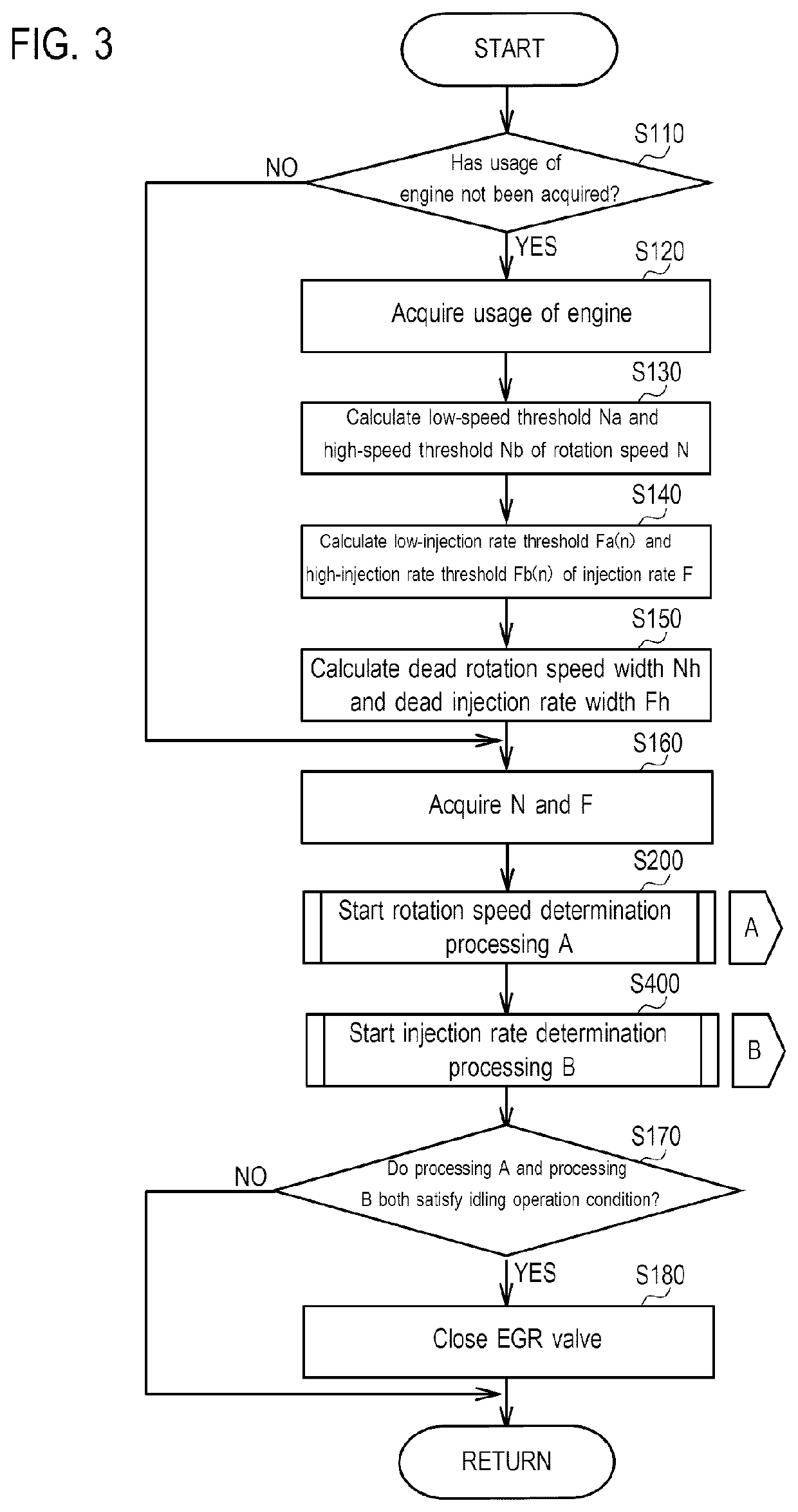
In an EGR device configured to reflux part of exhaust gas of the engine as EGR gas into intake air of the engine, an EGR valve configured to restrict a flow rate of the EGR gas is closed when rotation speed N of the engine is between a low-speed threshold and a high-speed threshold, and fuel injection rate is between a low-injection rate threshold and a high-injection rate threshold that are set for each rotation speed.

Description

CROSS-REFERENCE TO RELATED APPLICATIONS[0001]This application is the U.S. National Phase under 35. U.S.C. § 371 of International Application PCT / JP2015 / 052423, filed Jan. 29, 2015, which claims priority to Japanese Patent Application No. 2014-031006, filed Feb. 20, 2014. The disclosures of the above-described applications are hereby incorporated by reference in their entirety.TECHNICAL FIELD[0002]The present invention relates to an EGR device.BACKGROUND ART[0003]A conventionally known engine is provided with an EGR device that refluxes part of exhaust gas into intake air. Combustion temperature is reduced by the EGR device refluxing the exhaust gas (EGR gas), which contains a low concentration of oxygen, into the intake air, thereby reducing generation of nitrogen oxide. In such an engine, when the exhaust gas is refluxed for a long time in an idling operation state in which the exhaust gas contains unburned fuel, this unburned fuel adheres to the EGR device, potentially causing tro...

Claims


Application Information

Patent Timeline
Patent Type & Authority Patents(United States)
IPC IPC(8): F02D41/00F02D41/08F02D21/08
CPCF02D21/08F02D41/08F02D41/005F02D2021/083Y02T10/47Y02T10/40
Inventor YUKI, RYONAKANO, SATOSHIISHIGURO, TAKUYA
Owner YANMAR POWER TECHNOLOGY CO LTD
Learn More