
Transaxle

Active Publication Date: 2019-07-18
KANZAKI KOKYUKOKI MFG
View PDF0 Cites 0 Cited by
  • Summary
  • Abstract
  • Description
  • Claims
  • Application Information

AI Technical Summary

Benefits of technology

The invention provides a transaxle with a parking brake mechanism that can be reliably kept in its operating state to prevent unintended release of the brake. This ensures that the parking brake can be easily operated by the operator and can be safely maintained without causing excess force or damage. Additionally, the invention prevents unauthorized release of the brake due to external forces acting on the axle or parking brake arm.

Problems solved by technology

However, in the transaxle having such a parking brake mechanism, the case sometimes occurs in which when the parking brake mechanism is in operation, the gear applies counter torque to the parking brake mechanism to rotate the retaining pawl due to an external force acting on the axle, for example, and this unexpectedly releases the engagement between the gear and the retaining pawl.

Method used


Image

  • Transaxle
  • Transaxle
  • Transaxle

Examples


Embodiment Construction

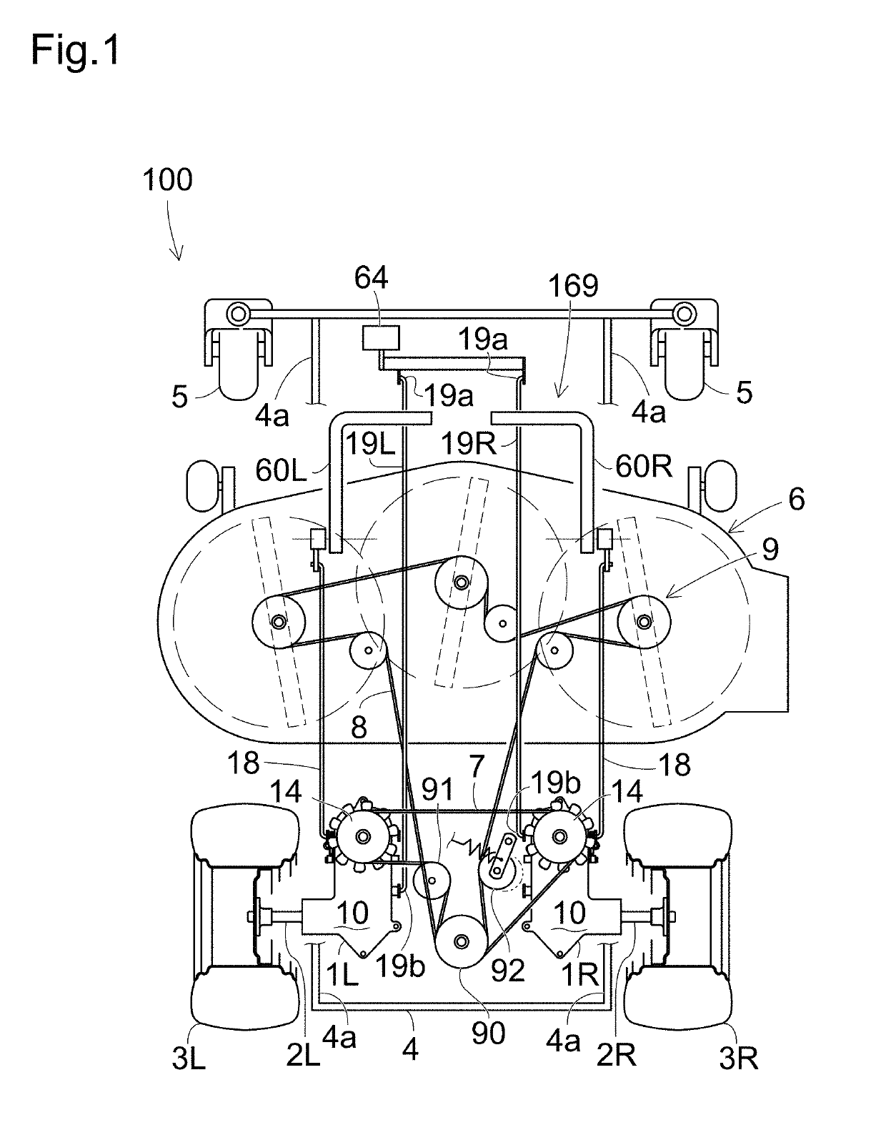
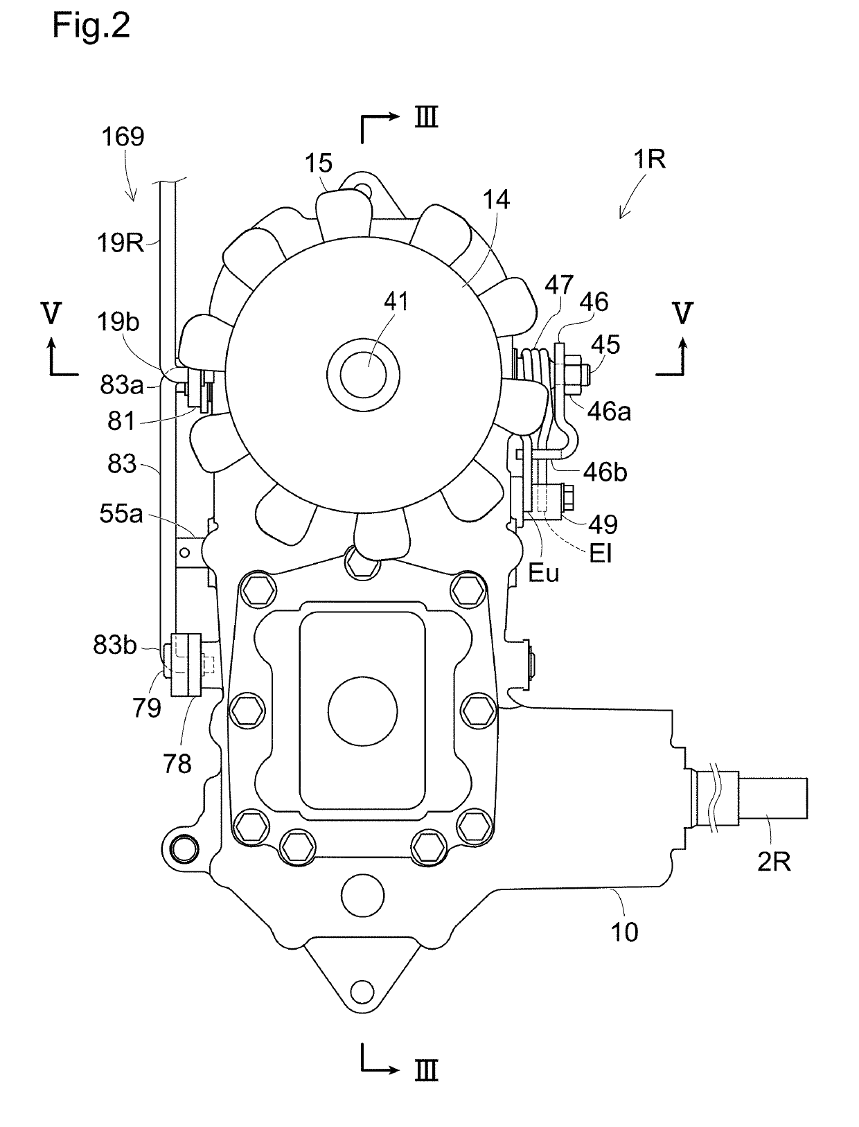
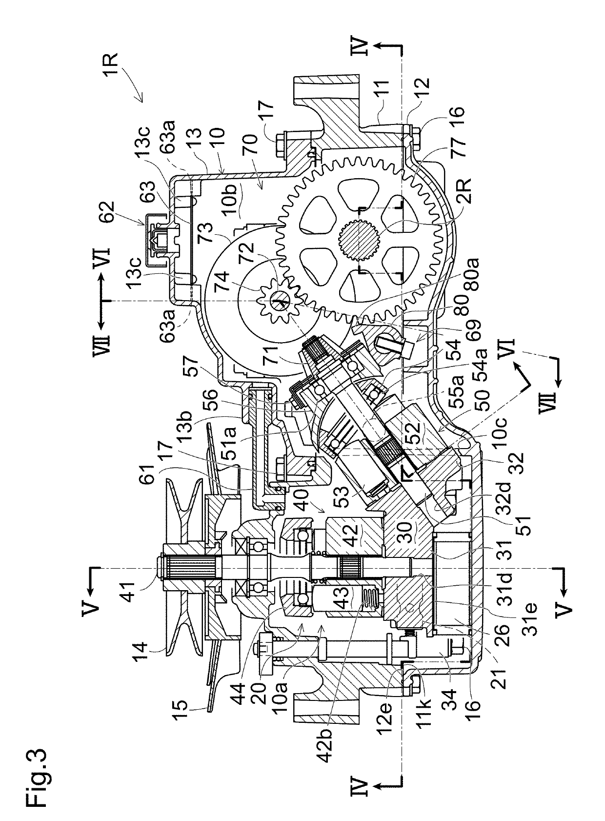
[0038]Referring to FIG. 1, a lawn mower (hereinafter simply referred to as “vehicle”) 100 serving as a typical zero-turn vehicle is equipped with right and left transaxle 1R and 1L carrying respective right and left axles 2R and 2L, and is equipped with right and left control levers 60R and 60L for controlling respective right and left transaxles 1R and 1L. Hereinafter, all the descriptions will be given on an assumption that right and left transaxles 1R and 1L are provided therebetween with a centerline disposed at the lateral middle position of vehicle 100 and extended in the fore-and-aft direction of vehicle 100, so that the side or direction of each of transaxles 1R and 1L close to the centerline is referred to as “proximal”, and the side or direction of each of transaxles 1R and 1L opposite or away from the centerline is referred to as “distal”. Therefore, right transaxle 1R has its left side as its proximal side, and has its right side as its distal side, and left transaxle 1L...


PUM


Abstract

A transaxle includes a braking unit disposed in the transaxle casing, the braking unit configured to brake the axle. The braking unit includes an operating shaft projecting from one side of the transaxle casing. A link mechanism of the transaxle is includes a relay arm rotatably pivoted on a shaft provided on the one side of the transaxle casing, a brake arm fixed to the operating shaft, the brake arm being configured to rotate between a braking position and an unbraking position of the braking unit together with the operating shaft, a first link configured to manipulate the relay arm, and a second link configured to join the relay arm to the brake arm. The link mechanism constrains motion of the brake arm through the second link such that an external force on the braking unit cannot cause an unexpected release from the braking state.

Description

CROSS-REFERENCE TO RELATED APPLICATION[0001]This application is a continuation-in-part application based on U.S. patent application Ser. No. 15 / 947,137, filed on Apr. 6, 2018, which is a continuation-in-part of U.S. patent application Ser. No. 14 / 738,410, filed on Jun. 12, 2015.BACKGROUNDField of the Invention[0002]The invention relates to a transaxle including a hydrostatic transmission (hereinafter, “HST”), an axle driven by the HST, a transaxle connected to a control lever for operating the HST, and a vehicle including the transaxle. The invention relates particularly to the transaxle including a mechanism that automatically returns the control lever to a neutral position. Specifically, this transaxle includes a parking brake mechanism that mechanically keeps the parking state of a vehicle.Related Art[0003]Conventionally, as disclosed in U.S. 2015 / 0007555 A1, there is a well-known hydraulic transaxle that serves as each of right and left transaxles carrying respective right and l...

Claims


Application Information

Patent Timeline
IPC IPC(8): F15B15/02B60K17/04F16H63/34F15B15/08B60T7/12B60T13/58B60T13/62F16H1/22B60K7/00
CPCF15B15/02B60K17/04F16H63/3416F15B15/08B60T7/12B60T13/588B60T13/62F16H1/22B60K7/0015B60K17/105B60T1/062B60Y2200/223B60Y2410/10
Inventor MATSUURA, JUNTSUKAMOTO, MICHIOSUGIMOTO, HIROSHIIIDA, MASARUOTA, TAKEHIRO
Owner KANZAKI KOKYUKOKI MFG
Learn More