
Device and method for cleaning microwave devices

a microwave device and cleaning technology, applied in the field of microwave fusing, can solve the problems of reducing the efficiency affecting the cleaning effect of the microwave device, and wasting unused microwave energy, and achieve the effects of reliable operation state, high degree of efficiency, and easy cleaning

Inactive Publication Date: 2006-04-25
EASTMAN KODAK CO
View PDF9 Cites 0 Cited by
  • Summary
  • Abstract
  • Description
  • Claims
  • Application Information

AI Technical Summary

Benefits of technology

[0004]The object of the invention is thus to provide a microwave device and a method for cleaning a microwave device, whereby the microwave device is easy to clean and thus has a reliable operating state with a high degree of efficiency.
[0005]This object is obtained by this invention wherein a microwave device is provided, in particular for the fusing of toner on a print substrate in a printing machine, with a microwave source providing an irradiation field and a resonator chamber. A microwave-penetrable material is included on the inside surfaces of the resonator chamber for the formation of a material layer that allows any dirt accumulating on it to protrude into the irradiation field. The cleaning of a microwave device is considerably simplified with the above-mentioned characteristics, as a result of which a consistent high degree of efficiency of the microwave device is obtained and the reliability of the microwave device is increased due to less downtime. The costs of expensive chemicals to clean the state-of-the-art microwave device, which are a health hazard and which give cause for concern about the environment, are saved.
[0006]In one of the embodiments of the invention, the material repels dirt and a device for supplying a first medium, which does not absorb the microwave irradiation, is provided for cleaning the resonator chamber of dirt essentially from the inside surfaces of the resonator chamber, whereby the dirt is heated by microwave irradiation and carried out of the resonator chamber by the first medium. The dirt-repelling material may comprise the economical material polytetrafluorethylene or polyvinylildene fluoride. A material thickness of 0.5 mm on the inside surfaces of the resonator chamber has proved to be advantageous with respect to material costs and efficiency.

Problems solved by technology

The problem is that, over time, dirt appears in the microwave device of the printing machine, which leads to loss of the unused microwave energy and reduces the efficiency of the microwave device.
Furthermore, the dirt can lead to arcing and cause malfunctions in the microwave device.

Method used


Image

  • Device and method for cleaning microwave devices
  • Device and method for cleaning microwave devices

Examples


Embodiment Construction

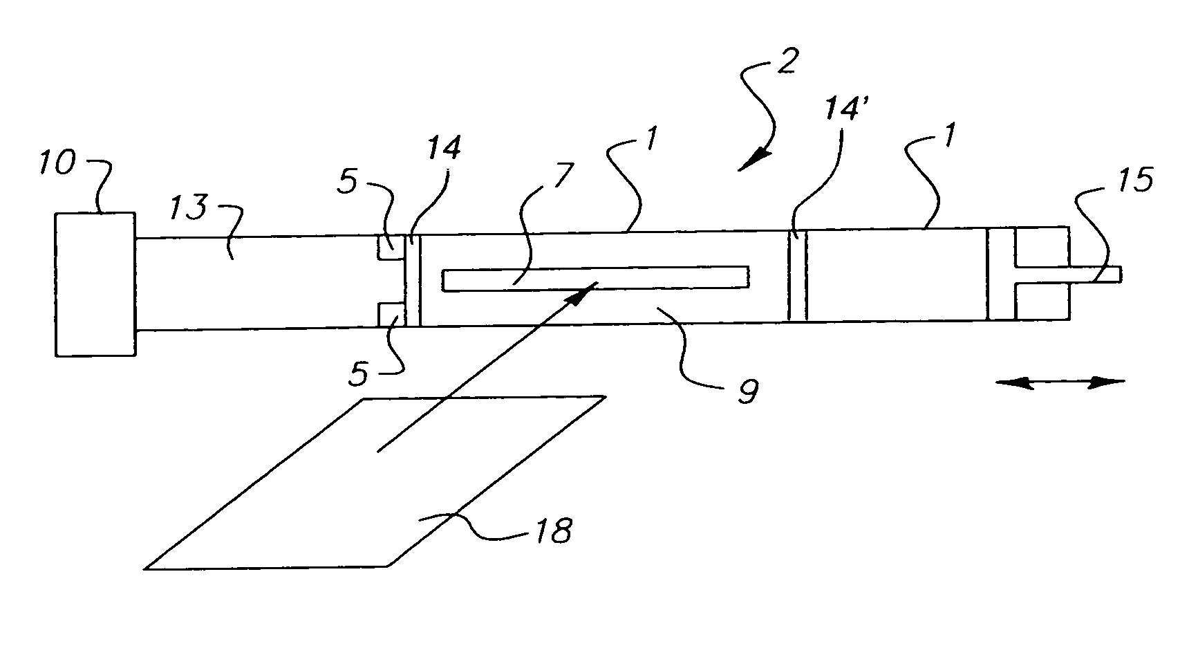
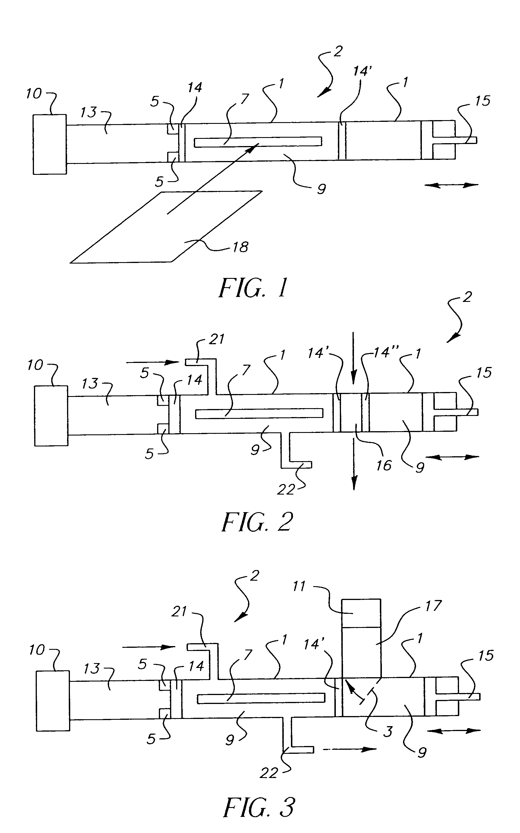
[0014]Referring now to the accompanying drawings, FIG. 1 shows a schematic lateral section of a microwave device 2 as an embodiment of the invention for fusing toner to a print substrate 18. A magnetron 10 is located on the left side of the microwave device 2 to generate microwaves. Attached to the magnetron 10 is an activating converter 13 to inject the microwaves into a resonator chamber 9. An orifice is located between the activating converter and the resonator chamber.

[0015]The resonator chamber 9 has a passage 7 in the lateral surface to conduct the print substrate 18 through the resonator chamber 9. The print substrate 18 is conducted through the resonator chamber 9 in the direction of the illustrated arrow. A corresponding passage is located in the opposite lateral surface of the resonator chamber 9 to guide the print substrate 18 out of the resonator chamber 9. On the right side of the resonator chamber 9 of the microwave device 2, there is a metal closing slide valve 15 tha...


PUM


Abstract

Cleaning a microwave device, in particular for drying print substrate in a printing machine, with a microwave source providing an irradiation field and a resonator chamber, wherein a microwave-penetrable material on the inside surfaces of the resonator chamber for forming a material layer that allows any dirt accumulated on it to protrude into the irradiation field.

Description

CROSS REFERENCE TO RELATED APPLICATIONS[0001]This is a divisional of U.S. application Ser. No. 10 / 422,317, filed on Apr. 24, 2003 now U.S. Pat. No. 6,878,911.FIELD OF THE INVENTION[0002]The invention relates to microwave fusing wherein a material on the inside surfaces of the microwave resonator allows dirt to be accumulated and to protrude into the irradiation field of the resonator.[0003]Microwave devices are used in many areas of technology. One application of microwaves is the heating of objects, such as microwave ovens in households. One particular application of microwave devices is as a fusing device in printing machines, whereby the image applied to a print substrate, by toner for example, is fused to the print substrate as the toner melts due to the heating of the toner and of the image carrier material by microwave energy, and the toner is interlocked with the print substrate. The problem is that, over time, dirt appears in the microwave device of the printing machine, whi...

Claims


Application Information

Patent Timeline
Patent Type & Authority Patents(United States)
IPC IPC(8): H05B6/70H05B1/00H05B6/80
CPCH05B6/6405H05B6/70H05B6/705H05B6/802H05B6/701H05B2206/046
Inventor BEHNKE, KNUTKRAUSE, HANS-OTTOMORGENWECK, FRANK-MICHAELROHDE, DOMINGOSCHULZE-HAGENEST, DETLEF
Owner EASTMAN KODAK CO
Learn More