Line-type grass cutting head with cutting blade

a cutting head and cutting blade technology, applied in the field of line-type grass cutting heads, can solve the problems of poor efficiency and unsafe use poor efficiency of the cutting head, and poor safety of the user, and achieve the effect of gradual cutting action

Active Publication Date: 2020-05-12
ARNETOLI MOTOR
View PDF28 Cites 0 Cited by
  • Summary
  • Abstract
  • Description
  • Claims
  • Application Information

AI Technical Summary

Benefits of technology

[0016]This allows to have a grass cutting head comprising two types of cutting members (line and blade), wherein the line may be elongated safely, without the need for the user to touch areas of the head where the blade cutting edges are arranged. Moreover, the blade position with respect to the cutting line housing, and, thus, with respect to the plane where the cutting line lies during the head operation, is better and more efficient with respect to the prior art grass cutting heads.
[0021]In some embodiments, the cutting blade extends annularly, entirely surrounding the rotation axis of the grass cutting head. For example, the cutting blade may be disc-shaped, with an edge provided with a smooth or toothed cutting edge, either on the entire extension thereof, or on single portions. The outer edge of the cutting blade is usually round. In other embodiments, the outer edge of the cutting blade is at variable distance from the rotation axis; namely, it has, for example, cutting edge portions extending in a spiral-like way. This allows having a more gradual cutting action.

Problems solved by technology

These heads do not allow the two cutting members (line and blades) to be used at the same time.
This head is poorly efficient and very unsafe for the user.
Also this grass cutting head is poorly efficient, uncomfortable and unsafe for the user.
Moreover, as members are not provided to control the cutting line elongation, in order to replace the cutting line length projecting from the housing the user shall handle the grass cutting head in the area where the cutting blades are arranged, and this makes the use of this grass cutting head unsafe and dangerous.

Method used


Image

  • Line-type grass cutting head with cutting blade
  • Line-type grass cutting head with cutting blade
  • Line-type grass cutting head with cutting blade

Examples


Embodiment Construction

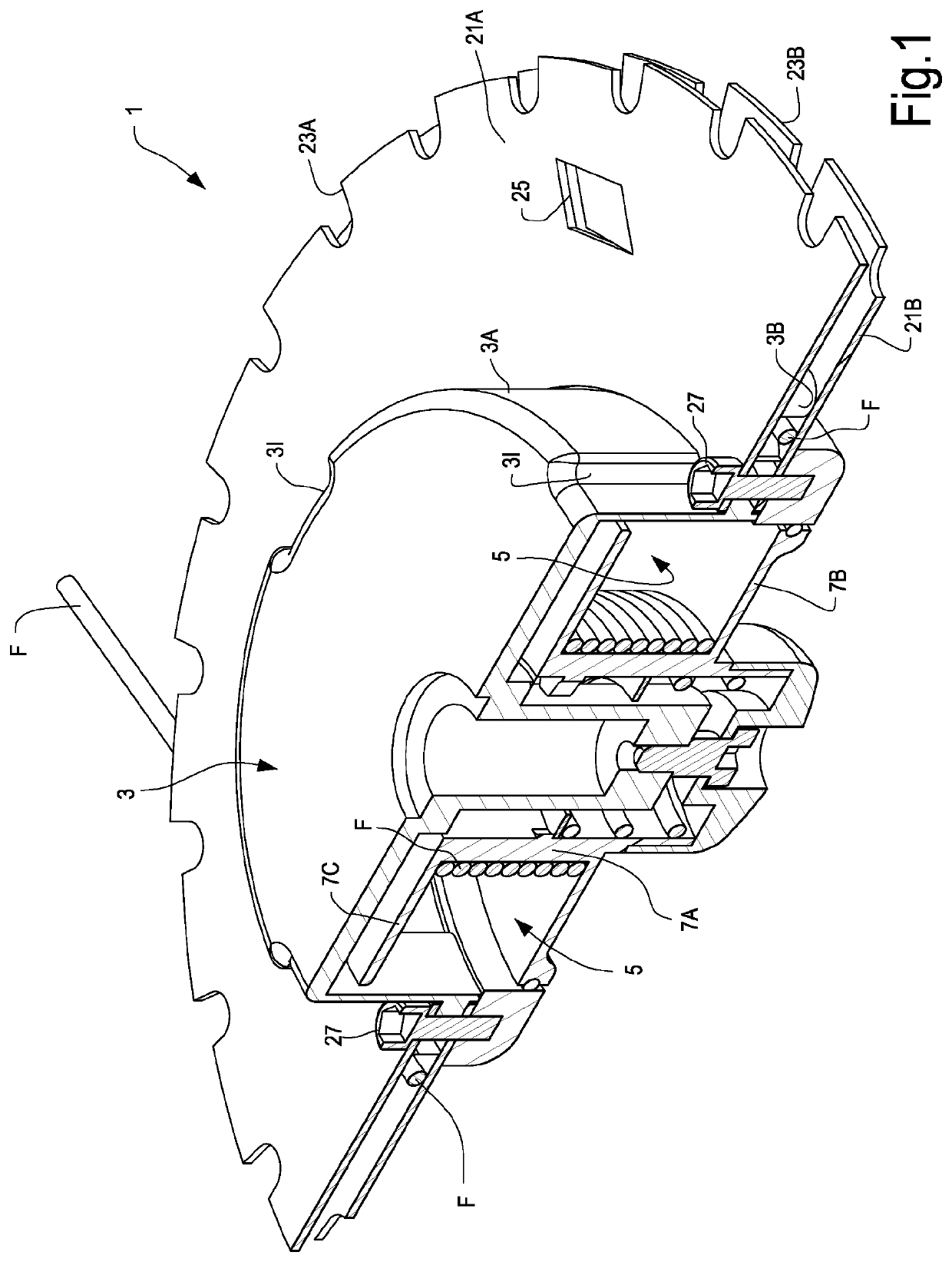
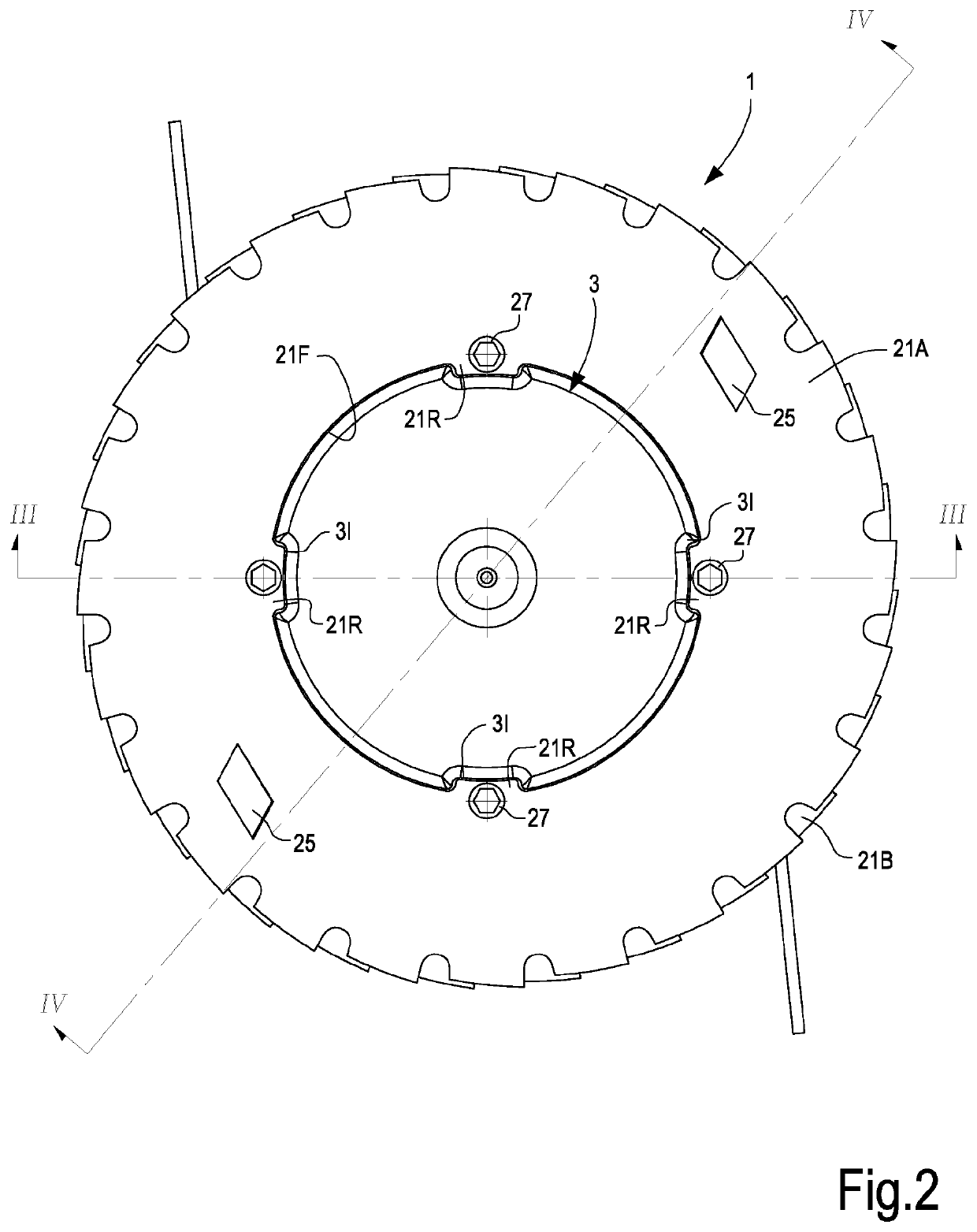
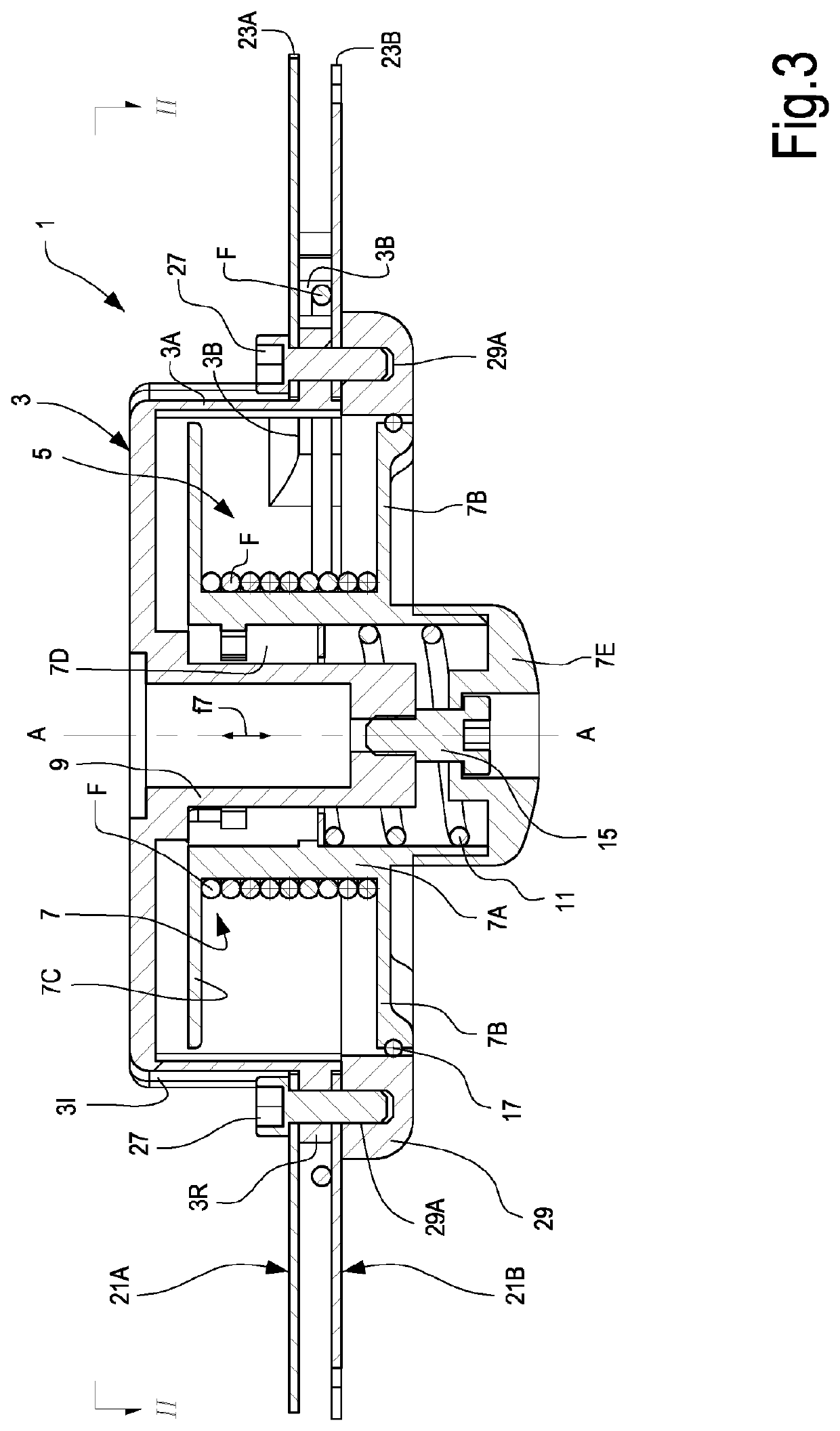
[0063]The detailed description below of example embodiments is made with reference to the attached drawings. The same reference numbers in different drawings identify the equal or similar elements. Furthermore, the drawings are not necessarily to scale. The detailed description below does not limit the invention. The protective scope of the present invention is defined by the attached claims.

[0064]In the description, the reference to “an embodiment” or “the embodiment” or “some embodiments” means that a particular feature, structure or element described with reference to an embodiment is comprised in at least one embodiment of the described object. The sentences “in an embodiment” or “in the embodiment” or “in some embodiments” in the description do not therefore necessarily refer to the same embodiment or embodiments. The particular features, structures or elements can be furthermore combined in any adequate way in one or more embodiments.

[0065]In the description below, the terms “...


PUM


Abstract

The grass cutting head (1), configured for rotation around a rotation axis, comprises a housing (3) for a cutting line (F); a space (5) inside the housing for winding a stock of cutting line; at least one hole (3B) in a side wall (3A) of the housing (3), through which the cutting line (F) passes from the inner space (5) towards the outside of the housing; At least one cutting blade (21) with at least one cutting edge (23) is associated with the housing (3) of the grass cutting head (1).

Description

FIELD OF THE INVENTION[0001]The embodiments disclosed herein relate to grass cutting heads and especially to line-type grass cutting heads.BACKGROUND ART[0002]Usually, so-called grass cutting heads are used to cut vegetation, for example grass, hedges or the like; these heads are applied to the drive shaft of a bush cutter actuated by an electric motor, an internal combustion engine or other actuating member, for example a hydraulic or mechanical arm actuated by means of a farm machine such as a tractor or the like. The fast rotation of the grass cutting head drives into rotation cutting members, with which the head is provided and which act on the vegetation, cutting it.[0003]In some prior art heads, cut is performed by means of a so-called cutting line, usually made of plastic, for example polyamide (nylon), and housed in a housing of the cutting head that forms an inner space to stock the cutting line. One or more ends of the line project from the grass cutting head; when the hea...

Claims


Application Information

Patent Timeline
Patent Type & Authority Patents(United States)
IPC IPC(8): A01D34/416A01D34/73
CPCA01D34/4166A01D34/4163A01D34/733
Inventor ARNETOLI, FABRIZIO
Owner ARNETOLI MOTOR
Why Eureka
Try Eureka