
System and method of managing tags associated with read voltages

a technology of read voltage and management method, applied in the direction of memory address/allocation/relocation, fault response, instruments, etc., can solve the problems of large bit error rate, failure or difficulty of the new set of read voltage, and degradation of the system performance of the non-volatile data storage device. achieve the effect of improving and improving efficiency

Inactive Publication Date: 2017-04-25
SANDISK TECH LLC
View PDF16 Cites 2 Cited by
  • Summary
  • Abstract
  • Description
  • Claims
  • Application Information

AI Technical Summary

Benefits of technology

This approach allows for efficient tracking and management of read voltages across multiple blocks, reducing errors and resource consumption by consolidating tags, thus enhancing the performance and memory efficiency of non-volatile data storage devices.

Problems solved by technology

During a read operation, a particular block which is associated with the last set of read voltages may fail decoding, may have a large bit error rate (BER) value, may require multiple decoding attempts before the particular block is decoded successfully, or may require decoding with multiple soft bits (e.g., two soft bits).
The “new” set of read voltages may be usable for the particular block that failed but other blocks (e.g., “older” blocks) which are associated with the last set of read voltages may still be readable with the last set of read voltages, but may fail or have difficulties with the new set of read voltages.
This process of triggering direct CVD computations and updating the set of read voltages may be repeated multiple times. Each computation of the direct CVD calculation requires resources and causes a delay (e.g., a few milliseconds) which may cause degradation in system performance of the non-volatile data storage device.
During operation of the data storage device, the controller may determine that a number of errors associated with blocks read using a particular tag is in excess of a threshold number of errors.
For example, as technology shrinks, variations between blocks becomes larger, and therefore tags determined for one set of blocks (e.g., in one plane of a memory) may not be suitable for reading a different set of blocks (e.g. in an adjacent plane of the memory).
While all pairs of tags may be searched to find a particular pair having a minimal L∞ difference norm, such an approach may be time consuming.

Method used


Image

  • System and method of managing tags associated with read voltages
  • System and method of managing tags associated with read voltages
  • System and method of managing tags associated with read voltages

Examples


Embodiment Construction

[0018]Particular embodiments of the present disclosure are described below with reference to the drawings. In the description, common features are designated by common reference numbers throughout the drawings.

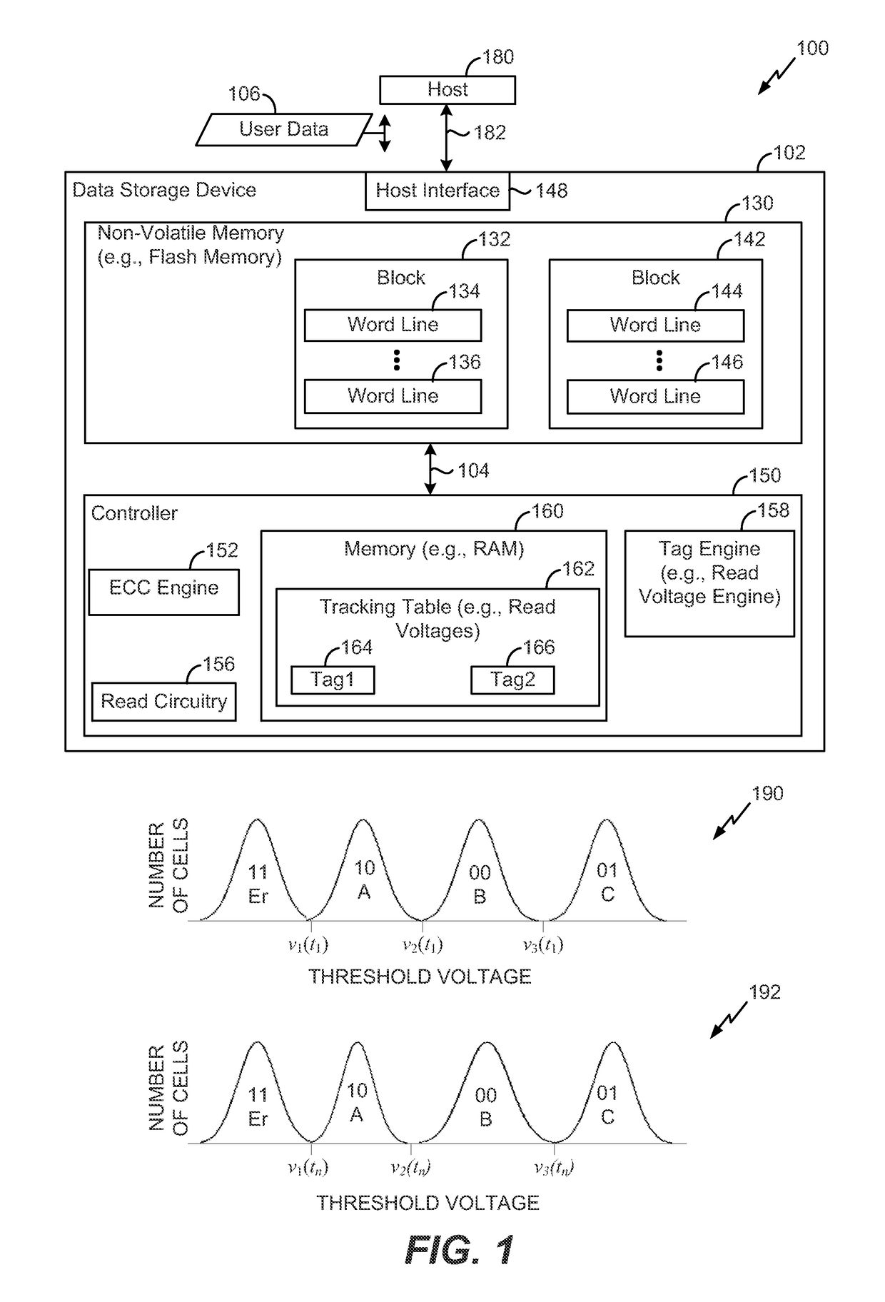
[0019]FIG. 1 is a block diagram of a particular illustrative embodiment of an electronic device 100 including a data storage device 102 and a host device 180. The data storage device 102 may be coupled to the host device 180 via a communication path 182, such as a wired communication path and / or a wireless communication path. The data storage device 102 may be embedded within the host device 180, such as in accordance with an embedded MultiMedia Card (eMMC®) (trademark of Joint Electron Devices Engineering Council (JEDEC) Solid State Technology Association, Arlington, Va.) configuration. Alternatively, the data storage device 102 may be removable from (i.e., “removably” coupled to) the host device 180. For example, the data storage device 102 may be removably coupled to the ho...


PUM


Abstract

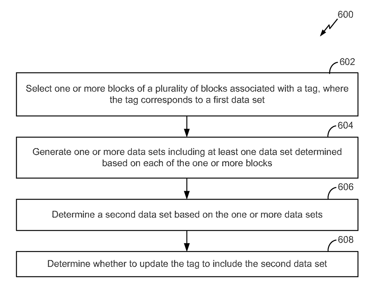
A data storage device includes a controller coupled to a non-volatile memory. The non-volatile memory is configured to store multiple tags that include a first tag and a second tag. The controller is configured to determine one or more candidate values associated with a candidate tag. The one or more candidate values may be determined based on an operation applied to the first tag and the second tag. The controller is further be configured to cause the non-volatile memory to remove the first tag or the second tag from the multiple tags.

Description

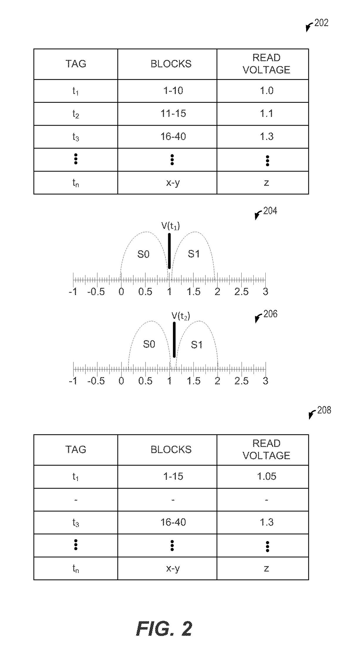
FIELD OF THE DISCLOSURE[0001]The present disclosure is generally related to managing tags associated with read voltages.BACKGROUND[0002]Non-volatile data storage devices, such as embedded memory devices (e.g., embedded MultiMedia Card (eMMC) devices) and removable memory devices (e.g., removable universal serial bus (USB) flash memory devices and other removable storage cards), have allowed for increased portability of data and software applications. Users of non-volatile data storage devices increasingly rely on the non-volatile storage devices to store and provide rapid access to a large amount of data. For example, a user may store large audio files, images, videos, and other files at a data storage device.[0003]Read voltages for reading a flash memory of a non-volatile data storage device are not the same for all of the blocks of the flash memory. Due to aging and cycling, the reading voltages tend to change over time, such that a first set of read voltages (e.g., a first tag) f...

Claims


Application Information

Patent Timeline
Patent Type & Authority Patents(United States)
IPC IPC(8): G06F12/00G06F13/00G11C29/50G06F11/07G06F11/10G06F12/02G06F12/121G11C11/56G11C16/26
CPCG11C29/50004G06F11/076G06F11/1016G06F11/1044G06F11/1072G06F12/0246G06F12/121G11C11/5642G11C16/26G06F2212/69G06F2212/7209G11C2029/5004
Inventor ALROD, IDANSHARON, ERANMEKHANIK, EVGENY
Owner SANDISK TECH LLC
Learn More