Prefabrication of pipe strings on board of pipe-laying vessels

a technology of pipe strings and pipe laying, which is applied in the direction of pipe laying and repair, cable laying vessels, mechanical equipment, etc., can solve the problems of adversely affecting the production cycle time, achieve better and more efficient, reduce flexibility in pipe processing stations, and facilitate better utilization of space available across the width

Active Publication Date: 2015-04-07
SAIPEM SPA
View PDF19 Cites 2 Cited by
  • Summary
  • Abstract
  • Description
  • Claims
  • Application Information

AI Technical Summary

Benefits of technology

[0026]As mentioned above, at least some of the pipe processing stations used in the first mode of operation perform a function in both the first and second modes of operation. Some of the pipe processing stations may perform the same function in the same location in both the first and second modes of operation. Having more pipe processing stations arranged to perform the same function in the same location in both the first and second modes of operation may reduce the amount of change required in order to allow the vessel to be adapted to switch its mode of operation between the first and second modes. Some of the pipe processing stations may perform the same function, but in a different location in both the first and second modes of operation. Some of the pipe processing stations may perform a different function, but in the same location in both the first and second modes of operation. Some of the pipe processing stations may perform a function in the first mode of operation, but be redundant in the second mode of operation.
[0047]Thus in accordance with embodiments of the second aspect of the invention, the welding of at least one of the joints of a triple joint pipe section is conducted in two separate pipe processing areas arranged along the length of the vessel. Conventionally, all welding operations on a single joint are conducted quickly in succession so that the weld material does not cool too much, and therefore, in arrangements of the prior art, the welding operations on a single joint are all conducted in the same pipe processing area on the vessel, the pipe sections not being moved along the length of the vessel between welding operations. Whilst the arrangement proposed by the present invention may deviate from such conventional arrangements, it is considered that splitting the welding process between first and second pipe processing areas may advantageously allow better and more efficient use of the pipe processing stations arranged across the width of the vessel. For example, such an arrangement may facilitate better utilisation of the space available across the width of the vessel, because the present invention allows the positioning of welding stations for a single joint one after the other in the longitudinal direction. In prior art arrangements, three welding stations are required to effect welding of a single joint (one station for performing pipe interior welding and two stations for performing pipe exterior welding). There may be room for only 4 or 5 welding stations across the deck within the available space in the pipe processing area. In such prior art arrangements, there is therefore insufficient room in one pipe processing area to fit in two sets of three welding stations, as would be required for the forming of a triple length pipe section (having two joints). The two sets of three welding stations therefore need to be provided in separate welding areas, which may therefore reduce the flexibility in the layout of pipe processing stations on deck.

Problems solved by technology

Whether during the prefabrication or during the manufacturing in firing line, welding operations are typically the most likely to cause delay in the pipelaying process.
Said operations can adversely affect the production cycle time.

Method used


Image

  • Prefabrication of pipe strings on board of pipe-laying vessels
  • Prefabrication of pipe strings on board of pipe-laying vessels
  • Prefabrication of pipe strings on board of pipe-laying vessels

Examples


Embodiment Construction

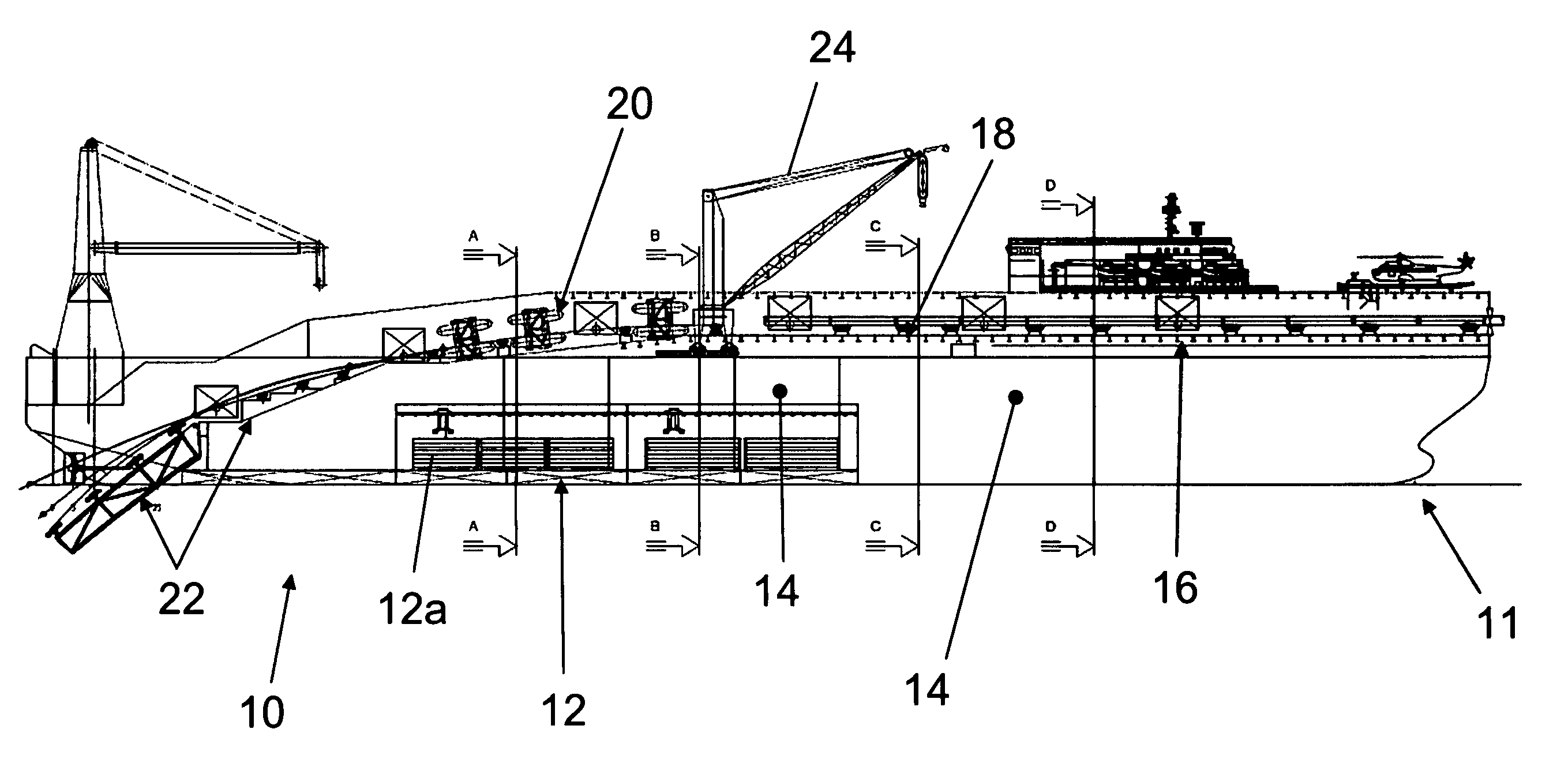
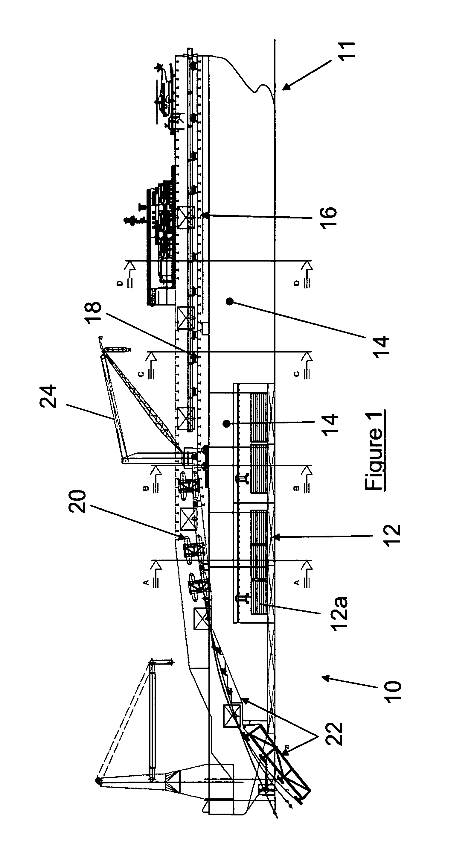
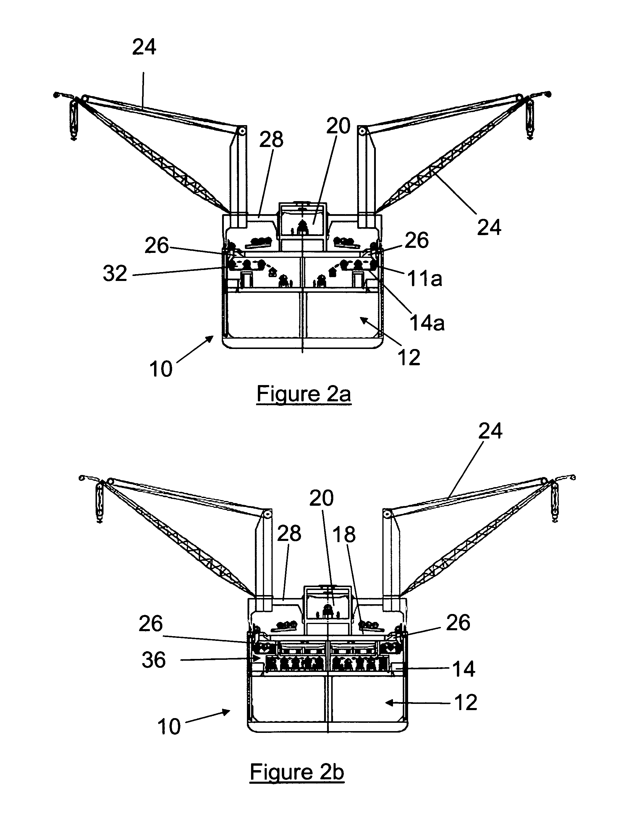
[0111]FIG. 1 shows a narrow mono-hull pipelaying vessel 10 having a width of about 40 m on the main deck and a length of about 330 m. The vessel 10 is arranged to fabricate, assemble and lay pipeline from single length pipe sections (“bars”). Such single length pipe sections are stored in a storage area 12 in the vessel's hold. Single length pipe sections are transported, when required, from the storage area 12 to a pre-fabrication deck 14, where such single length pipe sections are welded together to form either double joint pipe sections or triple joint pipe sections. (The pre-fabrication deck 14 is hidden from view in FIG. 1). The pipe storage and prefabrication facilities on board the vessel are symmetrically repeated across the vessel, so that the port-side facilities may be considered as a symmetrical reproduction of the starboard-side facilities. The pre-fabrication deck 14 produces jointed pipe sections having a length of 36 meters. The 36 meter jointed pipe sections are tem...


PUM


Abstract

A method of laying pipeline from a vessel (10) is disclosed. The vessel (10) includes many pipe processing stations (36, 42), arranged across the width of the vessel. In one embodiment, there are two pipe processing areas (38, 40) separated along the length of the vessel. The pipe processing stations (36, 42) may be operable in two modes of operation, for example, a first mode of operation where the vessel produces triple joint pipe strings (from three lengths of pipe section welded together) and a second mode of operation where double joint pipe strings are produced, for example, from two single length pipe sections having a significantly greater length than the single length pipe sections used in the first mode of operation. In one embodiment, a triple joint pipe section is part welded in one pipe processing area (38), then moved along the length of the vessel (10) to a different pipe processing area, where further welding operations are performed on the triple joint. In order for the vessel to operate in two modes of operation, the storage bin facilities (12) for storing single length pipe sections are configured to be able to accommodate different lengths of single length pipe section arranged end to end in a single bin.

Description

TECHNICAL FIELD[0001]The present invention relates to a method and a vessel for storage and / or prefabrication of pipes for subsequent use by a pipelaying vessel.BACKGROUND OF THE INVENTION[0002]Offshore pipelines, for example gas and or oil pipelines, are laid by vessels such as water crafts, barges, semi-submersibles or the like. Such pipelaying vessels are well known in the art. Examples in the art of such pipelaying vessels include U.S. Pat. No. 3,967,461, U.S. Pat. No. 4,257,718, U.S. Pat. No. 5,044,825 and U.S. Pat. No. 5,823,712.[0003]Typically, the pipeline is assembled in a firing line (the main production line) composed by a variety of operating stations, such as welding stations and testing stations. The pipeline is extended by joining pipe sections to the end of the pipeline. Such pipe sections (typically called “pipe strings”) are formed of a variety of single length pipe sections (typically called “bars”), which are preassembled either in on-shore yards or directly on b...

Claims


Application Information

Patent Timeline
Patent Type & Authority Patents(United States)
IPC IPC(8): F16L1/12F16L1/20
CPCF16L1/207B63B35/04
Inventor SCAINI, CRISTIANROSSIN, DAVIDE
Owner SAIPEM SPA
Why Eureka
Try Eureka