Cover mounting structure and display device
a display device and mounting structure technology, applied in non-linear optics, instruments, optics, etc., can solve the problems of reducing the likely expansion or contraction of the resin cover, and the likely cause of warpage in the cover, so as to reduce the basic performance of the display panel
- Summary
- Abstract
- Description
- Claims
- Application Information
AI Technical Summary
Benefits of technology
Problems solved by technology
Method used
Image
Examples
first embodiment
[1] First Embodiment
[1-1] The Cover Mounting Structure
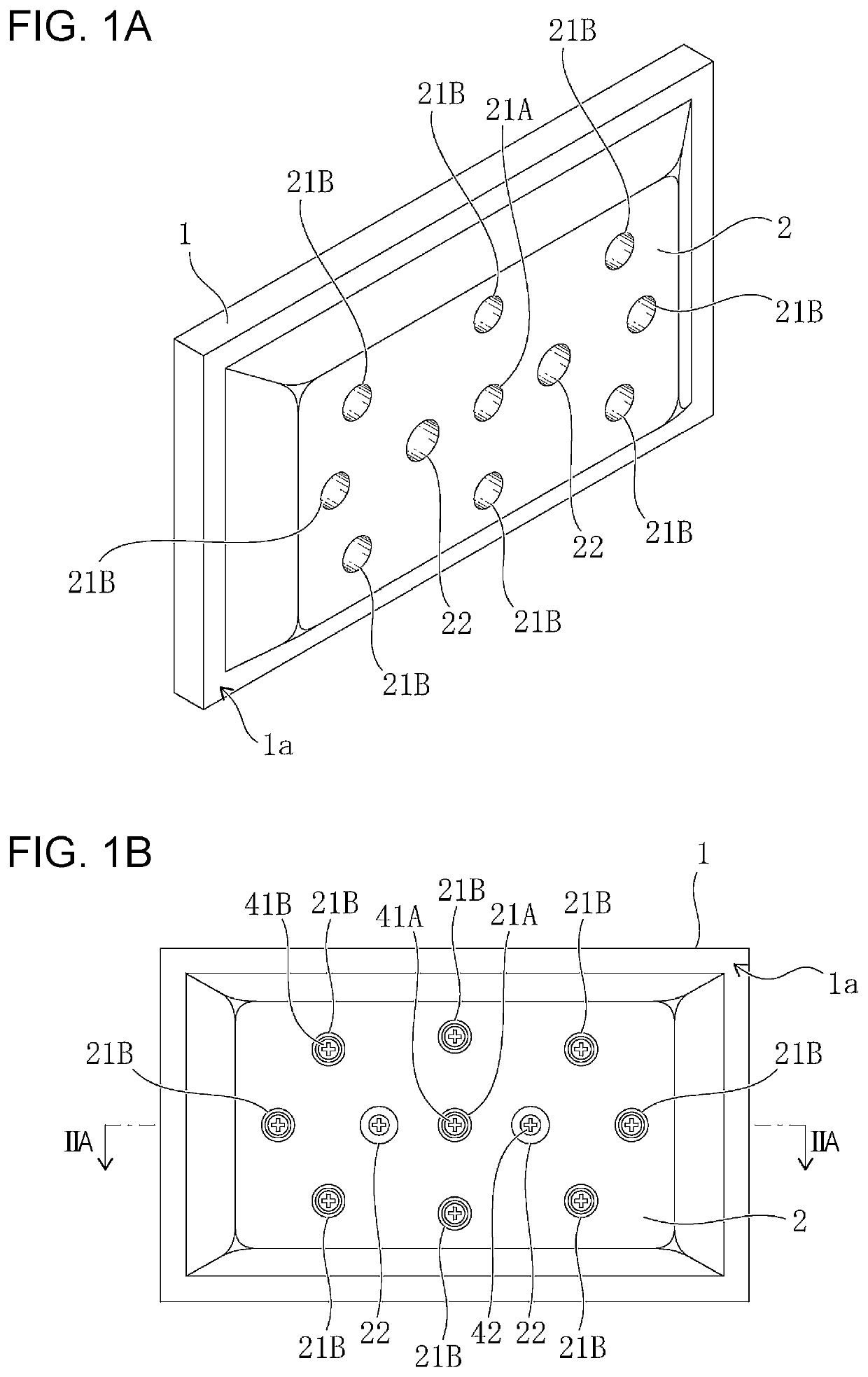
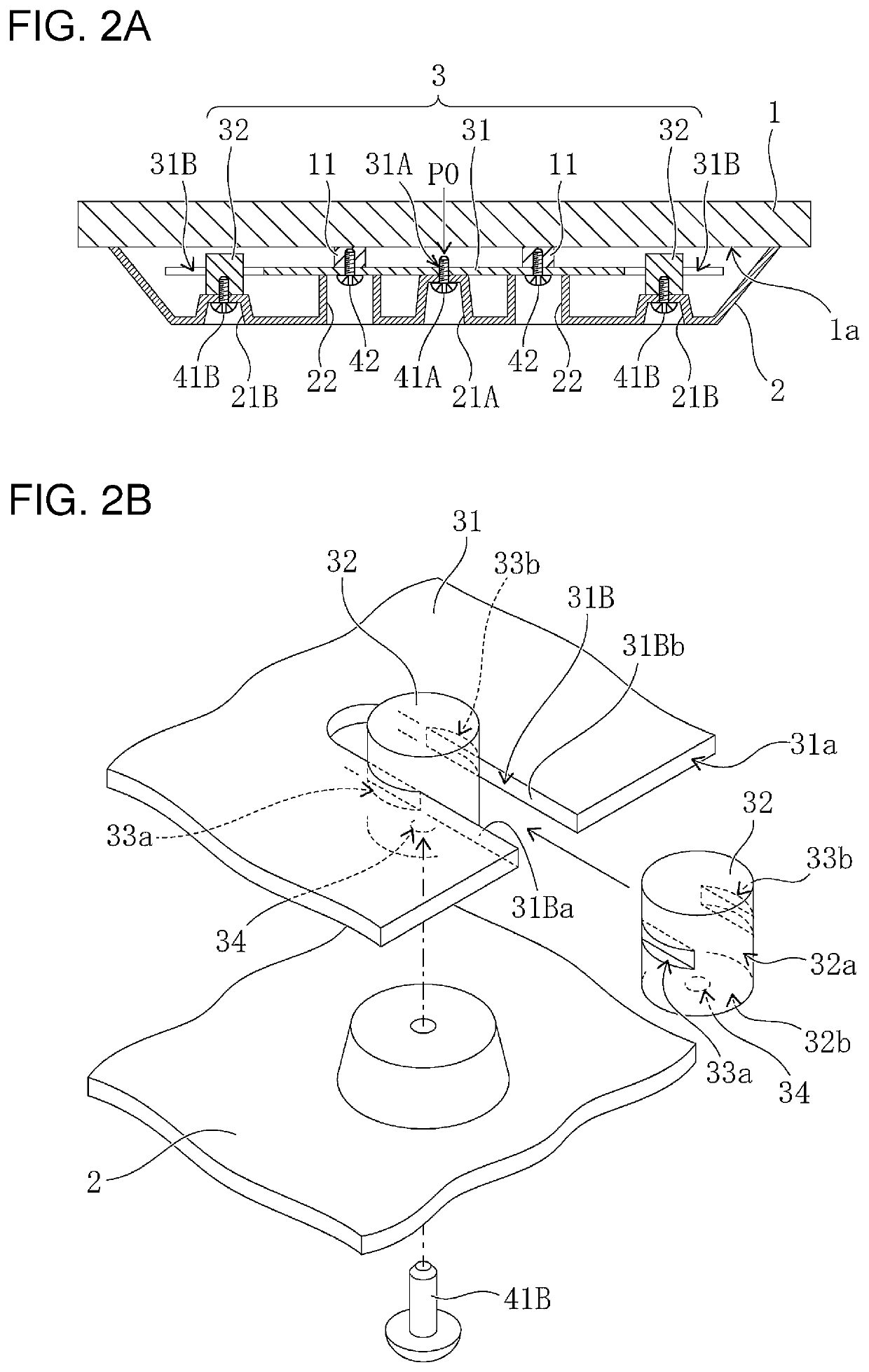
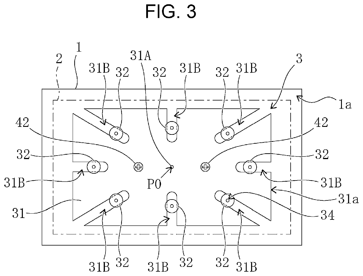
[0023]FIG. 2A is a sectional view of the cover mounting structure 3 according to a first embodiment, and FIG. 2B is an exploded perspective view of part of the cover mounting structure 3. FIG. 3 is a rear view of the display device with the cover 2 omitted. FIG. 2A is a sectional view taken along line IIA-IIA illustrated in FIG. 1B. As illustrated in FIGS. 2A to 3, the cover mounting structure 3 includes the support member 31 that supports the cover 2 and the sliding members 32 provided so as to be slidable relative to the support member 31. Both the support member 31 and the sliding members 32 are prepared separately from the cover 2. According to the present embodiment, eight of the sliding members 32 are provided for the support member 31 (see FIG. 3).
[0024]The support member 31 is a flat metal plate such as, for example, a metal sheet and secured to the rear surface 1a of the display panel 1 serving as the covering target. Sp...
second embodiment
[2] Second Embodiment
[2-1] The Cover Mounting Structure
[0042]FIG. 6A is a sectional view of the cover mounting structure 3 according to a second embodiment, and FIG. 6B is an exploded perspective view of part of the cover mounting structure 3. FIG. 7 is a rear view of the display device with the cover 2 omitted. As illustrated in FIGS. 6A and 6B, each of the sliding members 32 has a columnar shape having a slightly smaller width than the width of the guide slits 31B, and a flange-shaped flange portion 35 is formed along an end surface 32c of the sliding member 32 on the opposite side to the cover 2. Here, the flange portion 35 suppresses a movement toward the cover 2 side of the sliding member 32 inserted through the guide slits 31B. During the assembly of the display device, the flange portion 35 is brought into contact with (that is, hooked onto) the pair of edges 31Ba and 31Bb of the guide slit 31B, thereby being brought into engagement with the edges 31Ba and 31Bb.
[0043]Accordin...
third embodiment
[3] Third Embodiment
[0049]FIG. 9 is an exploded perspective view of part of the cover mounting structure 3 according to a third embodiment. As illustrated in FIG. 9, each of the sliding members 32 includes a pair of facing flat portions 351a and 351b inserted through a corresponding one of the guide slits 31B, a connecting flat portion 352 that connects end portions of the facing flat portions 351a and 351b to each other on the cover 2 side, and a pair of flange portions 353a and 353b. Such a sliding member 32 is able to be formed by, for example, bending a single flat metal plate.
[0050]The pair of flange portions 353a and 353b are formed at end portions of the respective facing flat portions 351a and 351b on the opposite side to the cover 2 so as to extend from the facing flat portions 351a and 351b on the pair of edges 31Ba and 31Bb of the guide slit 31B. Accordingly, the flange portions 353a and 353b suppress a movement toward the cover 2 side of the sliding member 32 inserted th...
PUM
| Property | Measurement | Unit |
|---|---|---|
| heat | aaaaa | aaaaa |
| distance | aaaaa | aaaaa |
| stress | aaaaa | aaaaa |
Abstract
Description
Claims
Application Information
 - R&D
- Intellectual Property
- Life Sciences
- Materials
- Tech Scout
- Unparalleled Data Quality
- Higher Quality Content
- 60% Fewer Hallucinations
Browse by: Latest US Patents, China's latest patents, Technical Efficacy Thesaurus, Application Domain, Technology Topic, Popular Technical Reports.
© 2025 PatSnap. All rights reserved.Legal|Privacy policy|Modern Slavery Act Transparency Statement|Sitemap|About US| Contact US: help@patsnap.com


