
Electrode assembly with projecting tab for battery and methods of forming same

a technology of electrode assembly and battery, which is applied in the direction of wound/folded electrode electrodes, cell components, sustainable manufacturing/processing, etc., can solve the problems of occupying additional space in the battery architecture, negatively affecting the electrical behavior of the cell housing, and affecting the performance of the battery

Active Publication Date: 2020-05-12
CUSTOM ELECTRONICS
View PDF6 Cites 0 Cited by
  • Summary
  • Abstract
  • Description
  • Claims
  • Application Information

AI Technical Summary

Benefits of technology

The patent describes an electrode assembly for a battery that includes a jelly roll electrode with multiple electrode sheets. The assembly also includes a tab that extends from the end of the electrode sheets and a conductive tab that is connected to the tab. The assembly is designed to be easily connected to a battery terminal, and the battery has a conductive casing for improved performance. An improved battery design is also provided that includes a cell cover with a second battery terminal that is connected to the first conductive tab. The technical effect is to provide a reliable and efficient battery design with improved performance and ease of use.

Problems solved by technology

Forming such a connection has proven to be a technical challenge, as improving some aspects of the connection may require sacrificing other qualities, e.g., electrical conductivity, shock resistance, real estate, seal strength, cell lifespan, and / or manufacturability.
Conventional cell architectures have proven unsatisfactory for providing these features in accordance with manufacturer and consumer criteria.
Some terminal components located between the electrode assembly and the cell housing may negatively affect electrical behavior within the cell housing.
Even when the terminals have minor effects on battery performance, the terminal components will inevitably occupy additional space in the battery architecture.

Method used


Image

  • Electrode assembly with projecting tab for battery and methods of forming same
  • Electrode assembly with projecting tab for battery and methods of forming same
  • Electrode assembly with projecting tab for battery and methods of forming same

Examples


Embodiment Construction

[0019]In the following description, reference is made to the accompanying drawings that form a part thereof, and in which is shown by way of illustration specific illustrative embodiments in which the present teachings may be practiced. These embodiments are described in sufficient detail to enable those skilled in the art to practice the present teachings and it is to be understood that other embodiments may be used and that changes may be made without departing from the scope of the present teachings. The following description is, therefore, merely illustrative.

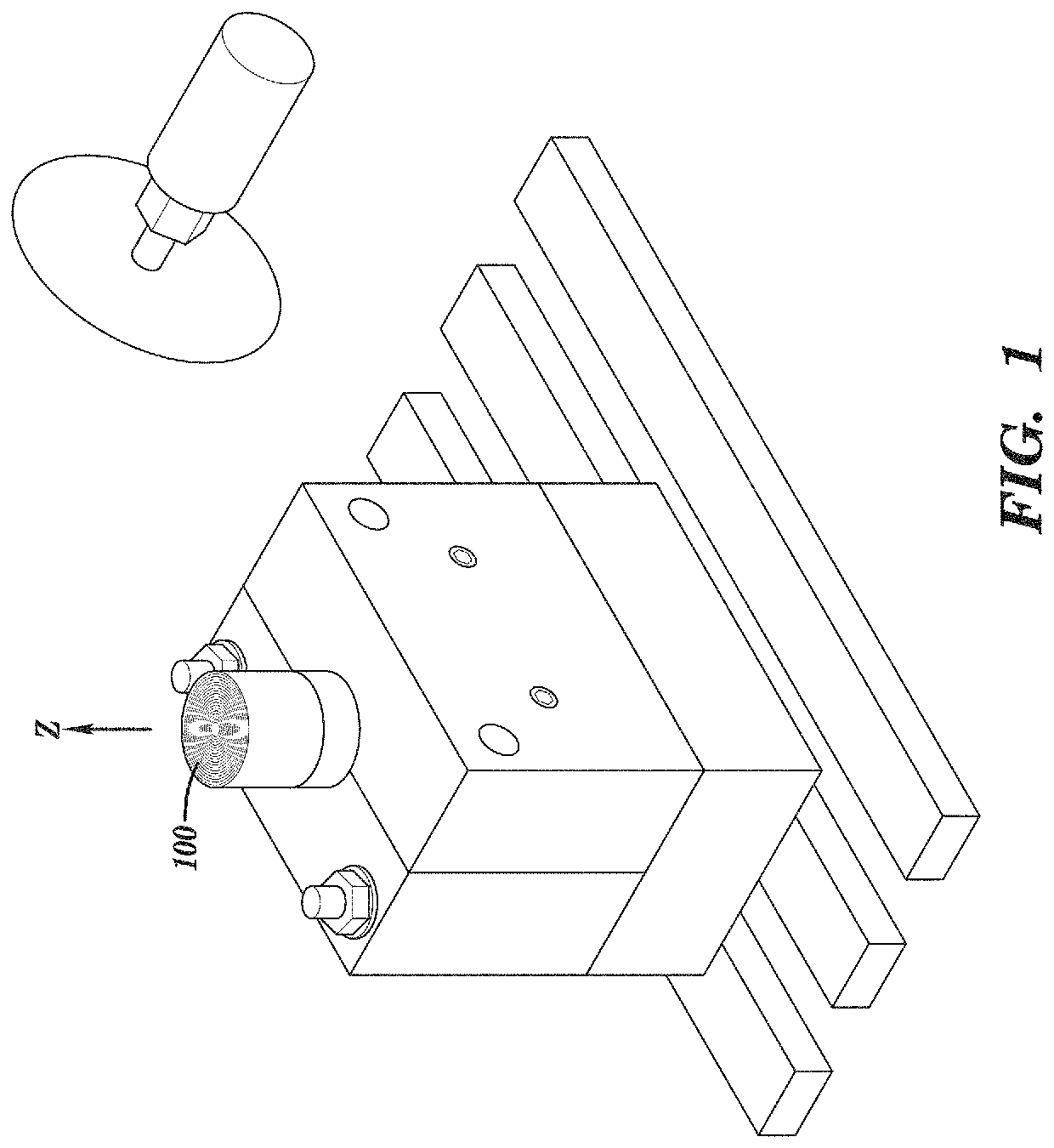
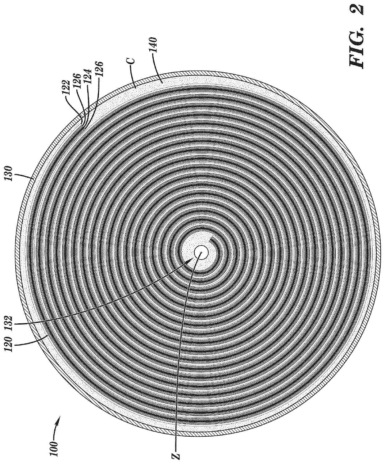
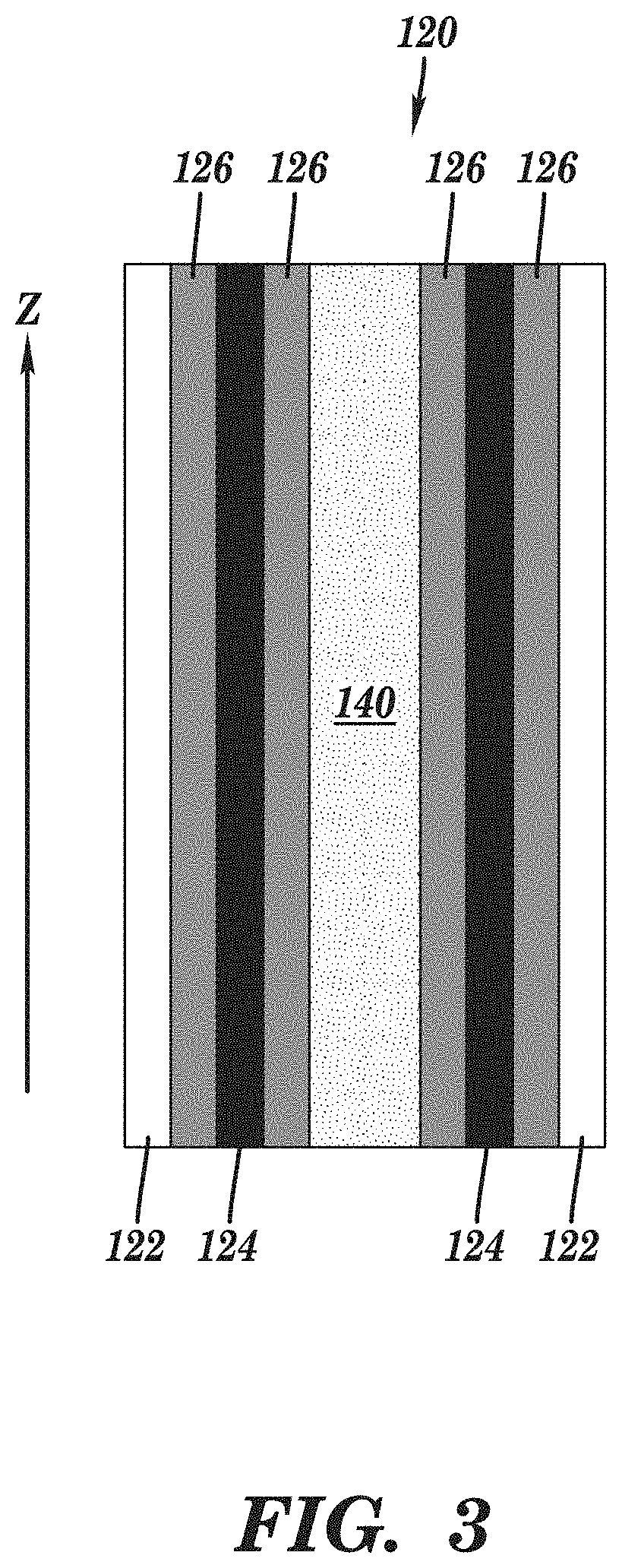
[0020]Referring initially to FIGS. 1 and 2 together, a preliminary electrode assembly (“assembly” hereafter) 100 to be processed in embodiments of the disclosure is shown. FIG. 1 provides a perspective view of assembly 100. FIG. 2 provides a plan view of assembly 100. Assembly 100 may take the form of a jelly roll electrode assembly, alternatively known as a wound cylindrical cell configuration as noted elsewhere herein. As...


PUM

PropertyMeasurementUnit
thicknessaaaaaaaaaa
lengthaaaaaaaaaa
lengthaaaaaaaaaa

Abstract

Embodiments of the disclosure provide an electrode assembly including: a jelly roll electrode having a plurality of electrode sheets, the plurality of electrode sheets including an anode sheet, a cathode sheet, and a separator separating the anode sheet from the cathode sheet, an electrolyte disposed between the anode sheet and the cathode sheet of the jelly roll electrode, and a tab projecting from an axial end of the plurality of electrode sheets, the tab including a subsection of the plurality of electrode sheets contacting each other at an axial end of the jelly roll electrode; and a first conductive tab coupled to the tab of the electrode assembly, wherein the first conductive tab is configured to electrically couple the electrode assembly to a battery terminal.

Description

BACKGROUNDTechnical Field[0001]The present disclosure relates to electrode assemblies for a battery. Specifically, embodiments of the disclosure provide electrode assemblies with a projecting tab and methods of forming the same.Related Art[0002]Batteries provide electrical energy in electronic systems. An electrode assembly for a battery includes two electrodes (anode and cathode, respectively), a separator between the electrodes, and opposite-polarity terminals for connecting the battery to the circuit. The fundamental elements of a battery may be formed using a wide variety of architectures. One such architecture is the wound cylindrical cell, adapted to fit inside a cylindrical housing. Wound cylindrical cells typically comprise several layers of films. The two active electrode materials of the cell (anode and cathode) may be coated onto thin layers of metal foil, e.g., having a thickness of approximately nine to approximately twenty micrometers. The metal foil may include alumin...

Claims


Application Information

Patent Timeline
Patent Type & Authority Patents(United States)
IPC IPC(8): H01M2/26H01M10/04H01M50/534H01M50/538H01M50/618H01M50/627
CPCH01M10/049H01M10/0431H01M2/263H01M10/0422H01M10/0409Y02E60/10H01M50/528H01M50/538H01M50/691Y02P70/50H01M50/534H01M50/618H01M50/627
Inventor CULVER, DUNCAN
Owner CUSTOM ELECTRONICS
Learn More