Vehicle, and method of controlling vehicle

a technology of vehicle and engine, applied in the direction of vehicle sub-unit features, electric propulsion mounting, gearing, etc., can solve the problems of driver's acceleration operation and engine speed not being in line with each other, driver's strange or uncomfortable feeling, etc., to reduce the shock that would occur upon engagement of the engagement mechanism, reduce the effect of the difference, and reduce the effect of the engine speed

Active Publication Date: 2020-05-19
TOYOTA JIDOSHA KK
View PDF7 Cites 3 Cited by
  • Summary
  • Abstract
  • Description
  • Claims
  • Application Information

AI Technical Summary

Benefits of technology

[0008]With the above configuration, when the traveling mode is switched between the low mode and the high mode, one of the first engagement mechanism and the second engagement mechanism, which is currently engaged, is released. Accordingly, the engine, first rotating machine, and drive wheels can be individually rotated. Namely, the engine speed can be controlled as needed. Therefore, the engine speed is less likely or unlikely to be excessively reduced, and can be changed in accordance with the required driving force. As a result, the driver is less likely or unlikely to feel strange or uncomfortable during switching of the traveling mode. Also, the rotational speed of the first rotating machine is controlled during switching of the traveling mode, so as to reduce a difference between the input rotational speed and output rotational speed of the engagement mechanism to be engaged. Since the engagement mechanism can be engaged in this condition, shock that would occur upon engagement of the engagement mechanism can be reduced or eliminated.
[0022]With the above configuration, when the traveling mode is switched between the low mode and the high mode, one of the first engagement mechanism and the second engagement mechanism, which is currently engaged, is released. Accordingly, the engine, first rotating machine, and drive wheels can be individually rotated. Namely, the engine speed can be controlled as needed. Therefore, the engine speed is less likely or unlikely to be excessively reduced, and can be changed in accordance with the required driving force. As a result, the driver is less likely or unlikely to feel strange or uncomfortable during switching of the traveling mode. Also, the rotational speed of the first rotating machine is controlled during switching of the traveling mode, so as to reduce a difference between the input rotational speed and output rotational speed of the engagement mechanism to be engaged. Since the engagement mechanism can be engaged in this condition, shock that would occur upon engagement of the engagement mechanism can be reduced or eliminated.

Problems solved by technology

Also, when the direct-coupling mode is set, all of the rotating elements of the power split mechanism rotate at the same rotational speed, and therefore, the accelerator operation of the driver and the engine speed may not conform with each other.
As a result, the driver may feel strange or uncomfortable.

Method used


Image

  • Vehicle, and method of controlling vehicle
  • Vehicle, and method of controlling vehicle
  • Vehicle, and method of controlling vehicle

Examples


Embodiment Construction

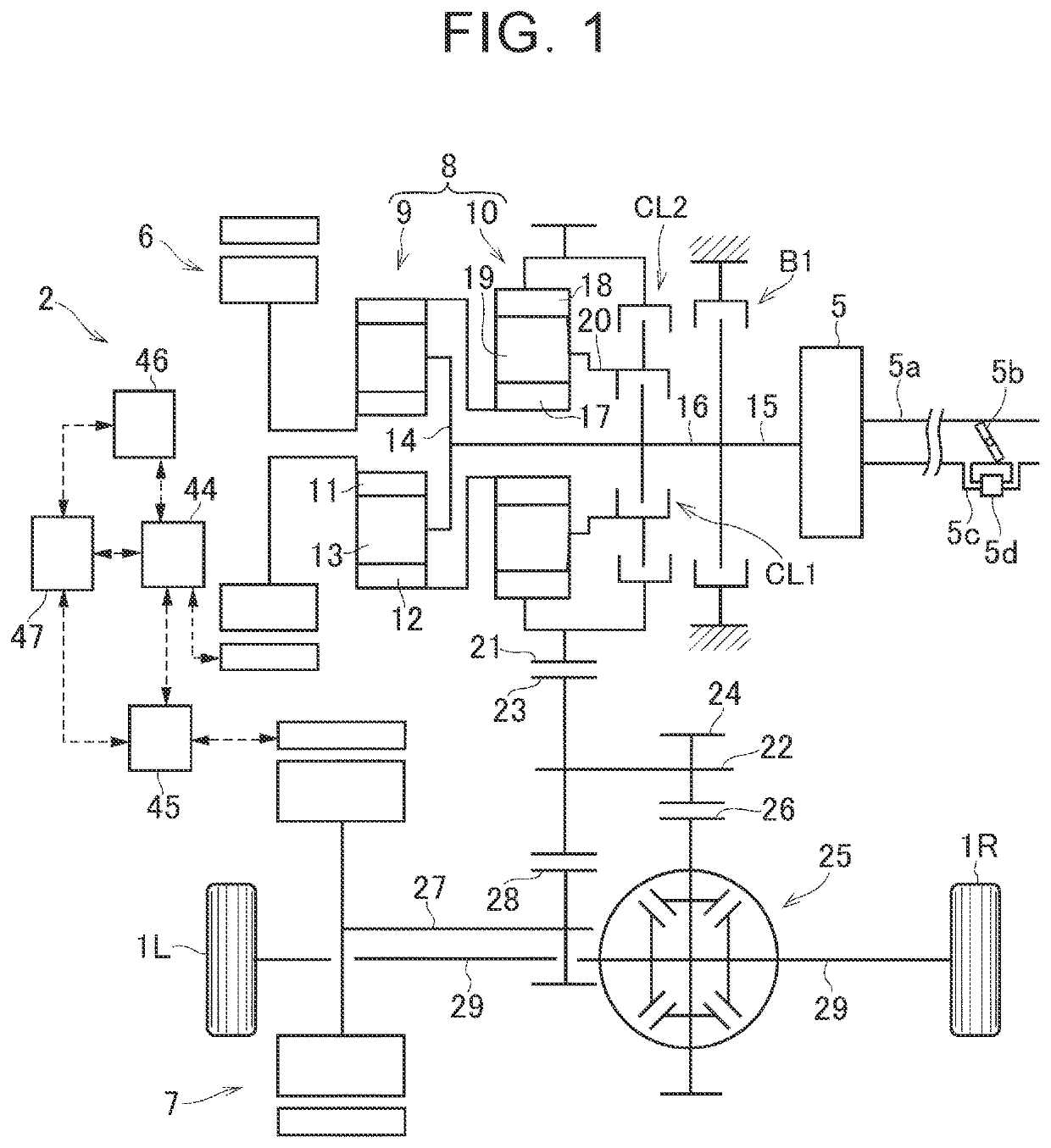
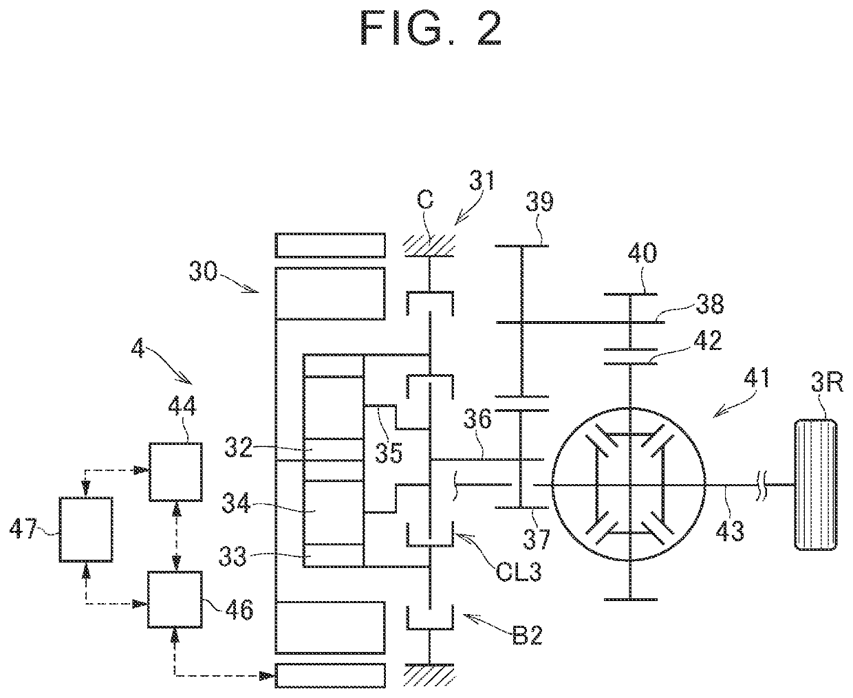
[0055]Referring to FIG. 1 and FIG. 2, one example of a vehicle according to one embodiment of the disclosure will be described. FIG. 1 shows a first drive unit 2 for driving front wheels 1R, 1L, and FIG. 2 shows a second drive unit 4 for driving rear wheels 3R, 3L. The first drive unit 2 is a so-called two-motor type drive unit including an engine 5 and two motors 6, 7 as drive power sources. A first motor 6 is provided by a motor (so-called motor-generator: MG1) having a function of generating electric power. The first drive unit 2 is configured such that the rotational speed of the engine 5 is controlled by the first motor 6, and a second motor 7 is driven with electric power generated by the first motor 6, while driving force delivered by the second motor 7 can be added to driving force for propelling the vehicle. The second motor 7 is provided by a motor (so-called motor-generator: MG2) having a function of generating electric power. The first motor 6 is one example of “first ro...


PUM


Abstract

A vehicle includes an engine, a transmission mechanism, and an electronic control unit. The electronic control unit performs first switching control when there is a request for switching from a low mode to a high mode. The first switching control is to release a first engagement mechanism, and switch a second engagement mechanism to an engaged state when a difference between input and output rotational speeds of the second engagement mechanism becomes equal to or smaller than a permissible value.

Description

INCORPORATION BY REFERENCE[0001]The disclosure of Japanese Patent Application No. 2017-243536 filed on Dec. 20, 2017 including the specification, drawings and abstract is incorporated herein by reference in its entirety.BACKGROUND1. Technical Field[0002]The disclosure relates to a vehicle that includes at least two engagement mechanisms, and is able to set two or more traveling modes by selectively engaging the engagement mechanisms, and also relates to a method of controlling the vehicle.2. Description of Related Art[0003]A power split mechanism described in Japanese Unexamined Patent Application Publication No. 2017-007437 (JP 2017-007437 A) principally consists of a single pinion type first planetary gear mechanism having a carrier to which an engine is coupled, and a sun gear to which a first motor is coupled, a single pinion type second planetary gear mechanism having a carrier to which a ring gear of the first planetary gear mechanism is coupled, and a ring gear to which drive...

Claims


Application Information

Patent Timeline
Patent Type & Authority Patents(United States)
IPC IPC(8): B60K6/365B60K6/387B60W10/08B60W20/30B60K6/445F16H3/72B60W10/02B60K1/00B60W20/40B60W20/20B60K1/02B60W10/06B60K6/38B60K6/52B60W30/188B60W10/115B60W10/18F16H3/54
CPCB60W10/08B60W10/02B60K1/00B60K1/02B60K6/445F16H3/728B60K6/387B60W20/30B60W20/20B60W20/40B60K6/365B60W10/06B60K6/52B60W2710/083B60W2710/065B60W10/115B60K2001/001F16H2200/2005B60K2006/381B60W30/1884F16H3/54F16H2200/2035B60W2710/021B60W2710/0644F16H2200/0034B60W2710/081B60W10/182B60Y2400/42F16H2200/2007B60Y2400/73Y02T10/62Y02T10/72B60K6/24B60K6/26B60K6/28B60K6/22B60K6/54B60K6/547B60W10/00B60W10/04B60W10/10B60W20/00
Inventor AOKI, KAZUMAIMAMURA, TATSUYAOSHIUMI, YASUHIROOKAMURA, YUKARIIWASE, YUJI
Owner TOYOTA JIDOSHA KK
Why Eureka
Try Eureka