Webbing adjustment device

a technology of webbing and adjustment device, which is applied in the direction of vehicle components, vehicle safety belts, semi-passive restraint systems, etc., can solve the problems of complex structure, multi-step adjustment, etc., and achieve the effect of short range of adjustment, complex structure and complicated operation

Active Publication Date: 2020-05-19
WANG LIANG HSIUNG
View PDF8 Cites 8 Cited by
  • Summary
  • Abstract
  • Description
  • Claims
  • Application Information

AI Technical Summary

Benefits of technology

[0007]The objective of the invention is to provide a webbing adjustment device that can solve the problems of the conventional height adjustment device including complex structure, short range of adjustment, multi-step adjustment, and complicated operation.
[0013]The webbing adjustment device is applied to the seat belt system in a vehicle. The guiding ring member is fixedly disposed on a support pillar in the vehicle and is located beside a seat in the vehicle. The webbing of the seat belt system is passed through the guiding ring of the guiding ring member. The frame and the slider moveably assembled in the cover are connected to two sections of the webbing divided by the guiding ring. When the webbing adjustment device is not in use, or a height position of a positioning point on the webbing does not need adjusting, the cover may be hung on the guiding ring to position the cover. The frame and the slider assembled in the cover are unlocked. The webbing can be pulled freely.
[0014]When the height position of a positioning point on the webbing needs adjusting, the cover is detached from the guiding ring member and is held by an occupant. The cover can move upwardly or downwardly in an intuitive way for adjusting the height position of the positioning point on the webbing. The relative motion between the frame and the slider is generated to unlock the webbing. The height position of the positioning point is adjusted steplessly. When the webbing adjustment device may be moved to a suitable position, the cover can be released. The webbing adjustment device locks the webbing automatically by the tension of the webbing for ensuring that the positioning point of the webbing is close to the height of the shoulder of the occupant. The webbing adjustment device is adapted to various types of vehicles. The webbing adjustment device is simplified in structure, easy in operation, and cost-effective in manufacture and assembly. The webbing adjustment device can be adjusted steplessly. The adjustment range of the webbing adjustment device is long. The webbing adjustment device is easy to operate and automatically locks the webbing.
[0015]The guiding ring is made of magnetic materials, and the cover has two magnets. The two magnets are respectively disposed on the two side plates for attracting the guiding ring. When the cover is hung on the guiding ring for positioning, the magnets on the cover can attract the guiding ring for increasing the positioning stability.

Problems solved by technology

In a conventional three-point seat belt system, when the webbing is fastened tightly, the height of the webbing near the shoulder of the occupant cannot be adjusted.
A conventional height adjustment device for the webbing of the seat belt system is adapted to a specific vehicle and has some defects, such as complex structure, short range of adjustment, multi-step adjustment, and complicated operation.

Method used


Image

  • Webbing adjustment device
  • Webbing adjustment device
  • Webbing adjustment device

Examples


second embodiment

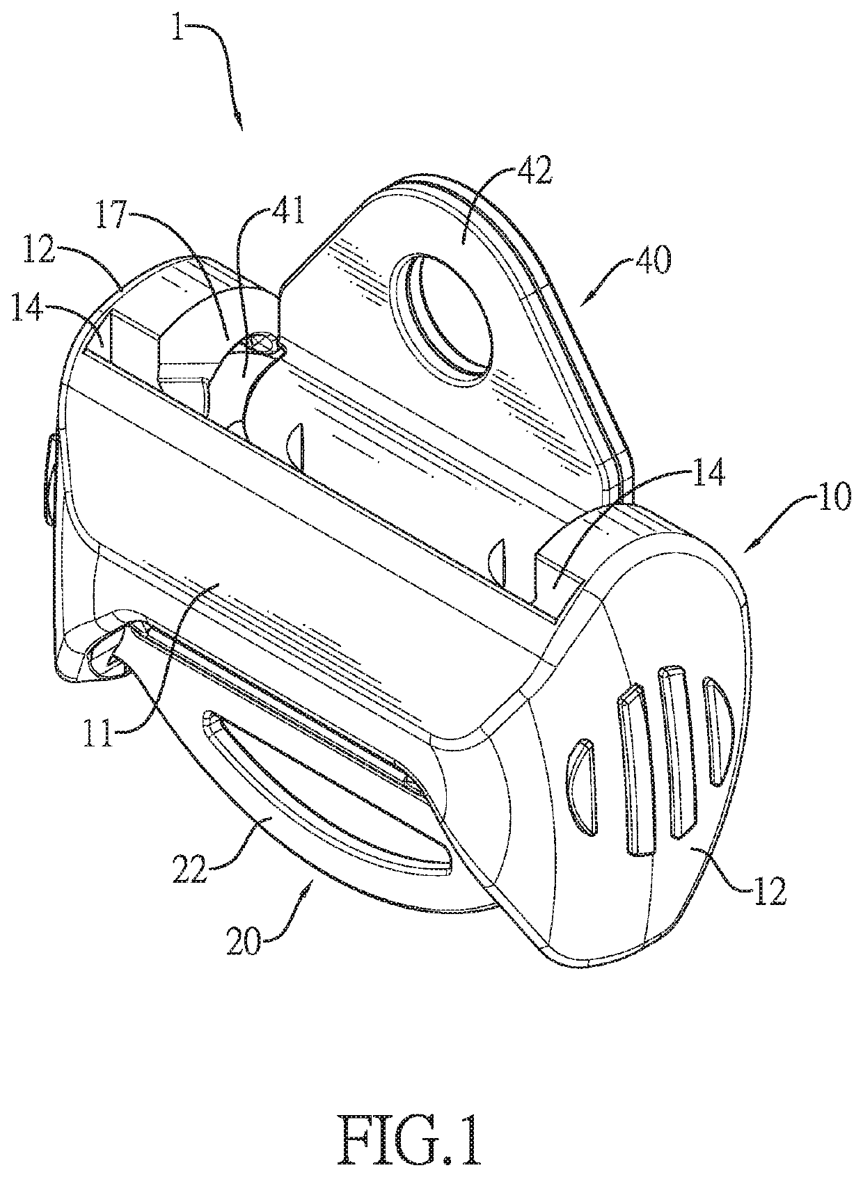
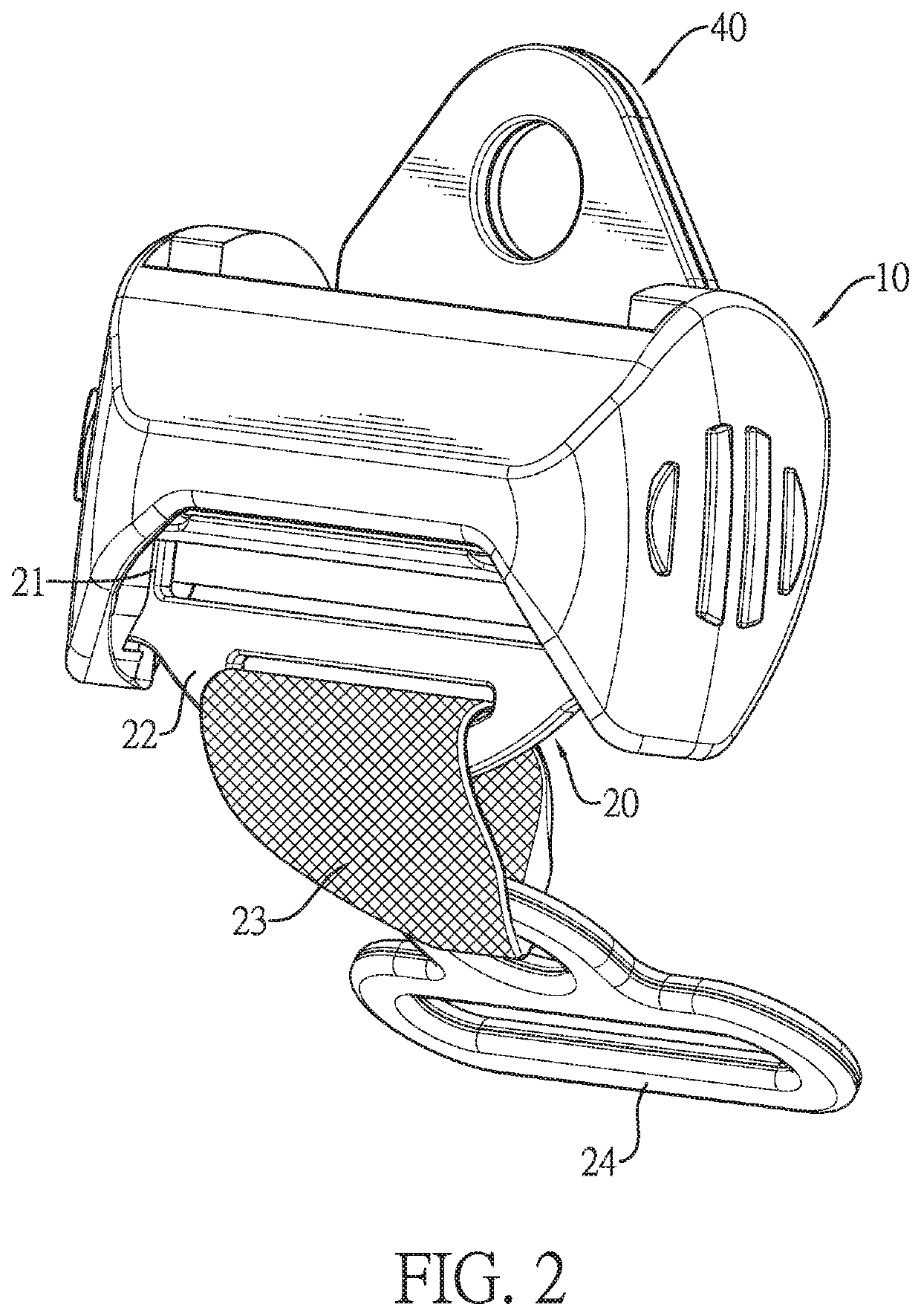
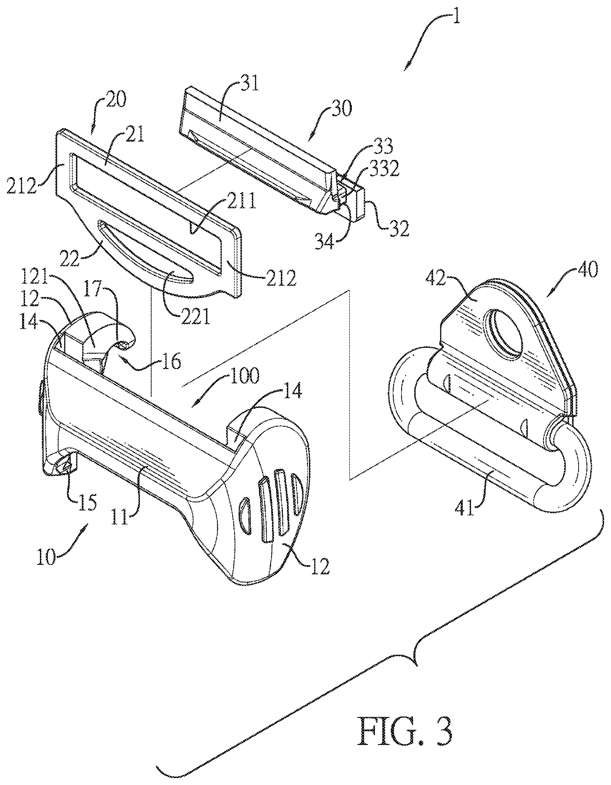
[0036]With reference to FIGS. 1, 3, and 4, the webbing 2 may be directly passed through the connecting hole 221 of the connecting portion 22. With reference to FIG. 2, in the webbing adjustment device, the webbing adjustment device has a connecting strap 23 and a connecting element 24. The connecting strap 23 is flexible and is connected to the connecting portion 22. The connecting element 24 is connected to the connecting strap 23. The webbing 2 is inserted through the connecting element 24. Therefore, the connecting portion 22 of the frame 20 is indirectly connected to the webbing 2 by the connecting strap 23 and the connecting element 24 in series connection. The connecting strap 23 is a strap having elasticity or no elasticity.

[0037]With reference to FIGS. 3 to 6, the slider 30 is located in the space 100 of the cover 10 and is moveably disposed in the body 21 of the frame 20. The slider 30 can move relative to the frame 20. The slider 30 has a first plate portion 31, a second p...

first embodiment

[0043]With reference to FIGS. 8 and 9, in the first embodiment, the webbing adjustment device 1 is applied to the seat belt system mounted in a vehicle. The positioning element 42 of the guiding ring member 40 is fixedly mounted on the pillar of the vehicle by a fixing element for fixing the webbing adjustment device beside a seat in the vehicle. The webbing 2 is pulled from a retractor 3 located beside the seat and is passed through the connecting portion 22 of the frame 20. Then, the webbing 2 is passed through the guiding ring 41 of the guiding ring member 40 and the through slot 331 of the slider 30 located in the frame 20. The webbing 2 has a front section 2A and a rear section 2B. The front section 2A of the webbing 2 is defined between the guiding ring 41 and the retractor 3. The rear section 2B of the webbing 2 is connected to the front section 2A of the webbing 2 and is sequentially passed through the guiding ring 41, the cover 10, the frame 20, the slider 3, and a tongue 4...


PUM


Abstract

A webbing adjustment device has a cover, a frame, a slider, and a guiding ring member. The frame is up and down moveably disposed in the cover. The slider is located in the cover, is moveably disposed in a body of the frame, and has a through slot formed through the slider. Webbing inserted through the through slot is locked or unlocked by a relative motion between the frame and the slider. The guiding ring member is detachably disposed on the cover, and has a guiding ring and a positioning element connected to the guiding ring. The webbing is inserted through the guiding ring. The cover is detachably hung on the guiding ring. The webbing adjustment device can lock the webbing automatically by the tension of the webbing.

Description

[0001]This application claims the benefit of Taiwan Patent Application No. 106140151, filed on Nov. 20, 2017, the entire contents of which are incorporated herein by reference.BACKGROUND OF THE INVENTIONField of the Invention[0002]The present invention relates to a webbing adjustment device, and more particularly to a webbing adjustment device to adjust a height of an upper area of a three-point seat belt system of a vehicle.Description of Related Art[0003]For protecting every occupant in a vehicle, each vehicle has to install a seat belt system. In general, a retractor of the seat belt system is disposed on a support pillar in the vehicle and is located beside a seat in the vehicle. A webbing of the seat belt system is pulled out from the retractor of the seat belt system. The webbing of the seat belt system is passed through a guiding ring of the seat belt system, and then the webbing is obliquely passed the front of the occupant's torso. A tongue mounted around the webbing is ins...

Claims


Application Information

Patent Timeline
Patent Type & Authority Patents(United States)
IPC IPC(8): B60R22/20B60R22/26B60R22/02B60R22/19A44B11/25B60R22/10B60R22/18
CPCB60R22/20A44B11/2557B60R22/023B60R22/19B60R22/26B60R22/105B60R22/024B60R2022/1818
Inventor WANG, LIANG-HSIUNG
Owner WANG LIANG HSIUNG
Why Eureka
Try Eureka