
Cable through panel feedthrough connector with release buttons

Active Publication Date: 2020-05-26
HAMPTON ELECTRIC LLC
View PDF38 Cites 0 Cited by
  • Summary
  • Abstract
  • Description
  • Claims
  • Application Information

AI Technical Summary

Benefits of technology

[0009]The pressure tab has a pressure prong on the tab that is bent away from the axis with the free end tip either toward the trailing end or alternatively bent with the free end tip toward the leading

Problems solved by technology

Therefore, it should be appreciated that completing all of these connections can be very time consuming, when contractors usually use such mentioned tools on each connection.
Although using the aforementioned snap engagement connectors eliminates using tools for installation, they typically require a lot of effort to snap them on the junction box.
Furthermore, if there is a need fo

Method used


Image

  • Cable through panel feedthrough connector with release buttons
  • Cable through panel feedthrough connector with release buttons
  • Cable through panel feedthrough connector with release buttons

Examples


Example

DETAILED DESCRIPTION OF THE DRAWINGS

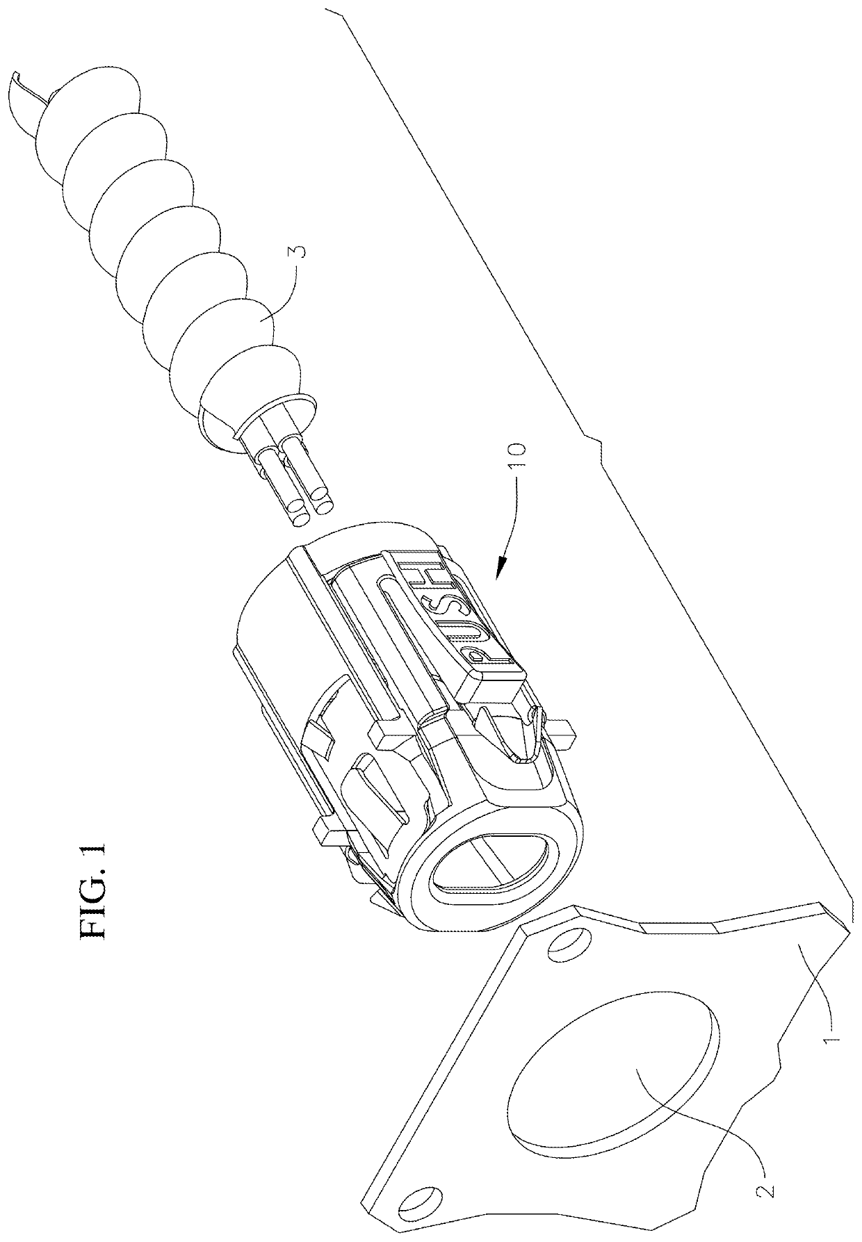
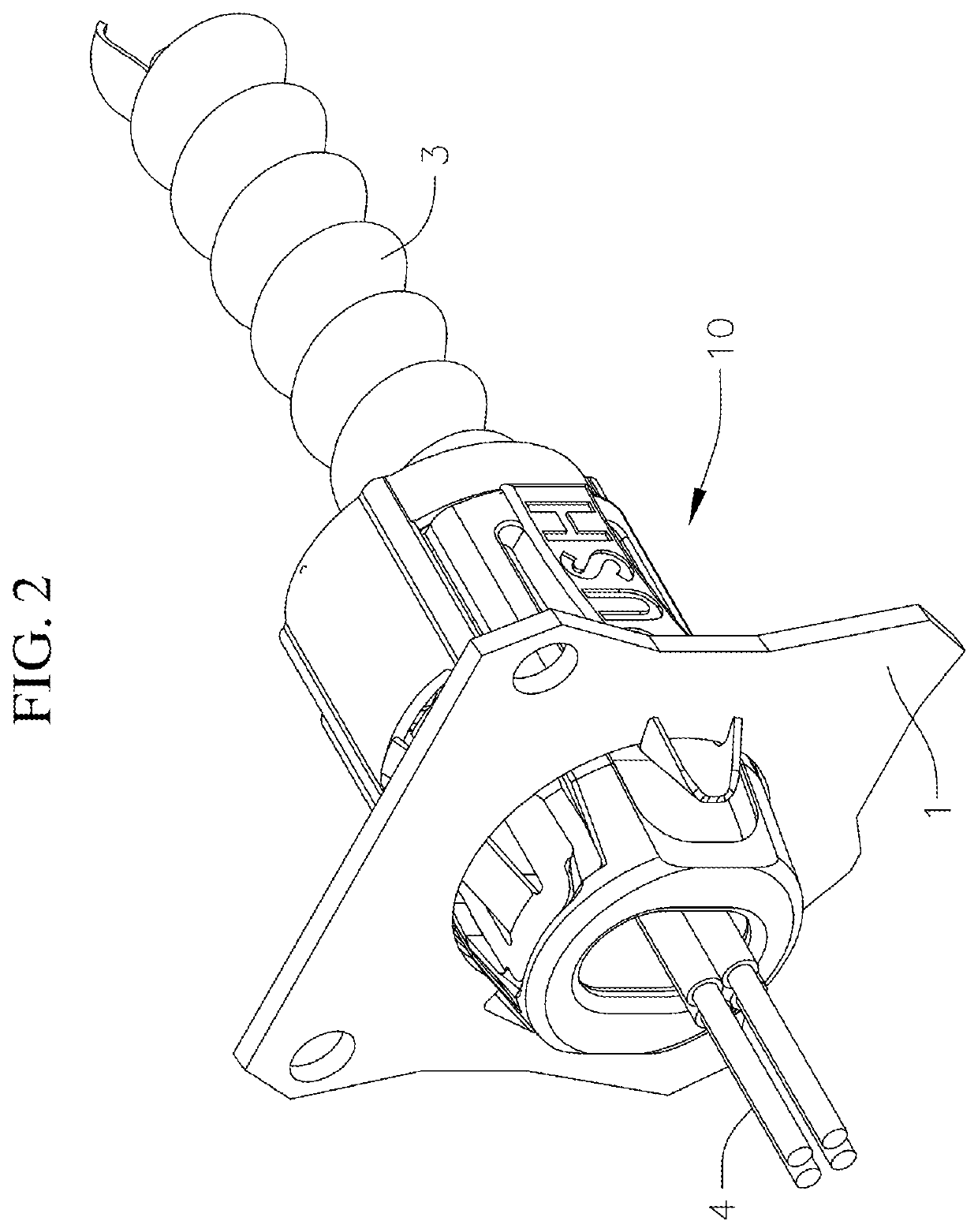
[0016]An embodiment of the present invention is an electrical connector 10 as illustrated in FIGS. 1-4. FIG. 1 is an isometric view of the connector 10 aligned with a knock out hole or aperture 2 in an electrical panel 1 and with an electrical cable 3 prior to connection. FIG. 2 is an isometric view of the connector 10 after connection. As can be seen in these figures, the connector 10 secures into the aperture 2 of the panel 1 and securely receives the cable 3. In practice, the cable 3 will support a plurality of electrical wires 4, which may be already present in the cable 3 or installed through the cable 3 later.

[0017]The transition from the pre-connection state in FIG. 1 to the post-connection state in FIG. 2 involves two operations. The cable 3 is pressed into locking engagement with the connector 10, and then the connector 10 is snapped into locking engagement in the aperture 2 of the panel 1. Alternately, the order of these operations can b...


PUM


Abstract

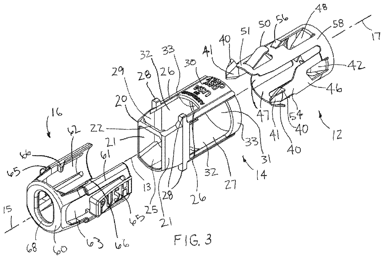
The present invention is a connector for connecting an electrical cable having cladding to an aperture in an electrical panel. The assembled connector has a spring, a shell, and a insulator along a longitudinal axis. The spring has a base from which two insertion tabs extend coaxial with the axis and the shell has two side walls to prevent over-insertion of the cladding into the connector. The insertion tabs of the spring have hook latches extending past the insulator that lock the connector in the panel, and the insulator has pressure buttons for flexing the insertion tabs during insertion and removal of the connector to the electrical panel.

Description

BACKGROUND OF THE INVENTIONTechnical Field[0001]The present invention relates generally to connectors for connecting electrical cables and flexible conduits to electrical panels, and more particularly to an improved connector that allows easier insertion of the connector into the panel and precise positioning of the conduit of the cable within the connector.Background Art[0002]The present invention relates to connectors for connecting electrical cables having flexible conduits to electrical panels. The invention is an improved connector that allows easier insertion of the electrical cables into a trailing end of the connector and the connector into the electrical panel, and providing precise positioning of the flexible conduit within the connector so that the conductors of the cable can easily pass through the connector into the panel.[0003]Historically, armored cable (AC) or metal-clad cable (MC) has been connected to a panel by a tubular connector including a leading end having a ...

Claims


Application Information

Patent Timeline
IPC IPC(8): H02G3/06H01R13/74H01R13/627H01R9/05H01R24/56
CPCH01R24/564H01R9/0524H01R13/743H01R9/0527H01R13/6271H02G3/0641
Inventor JAFARI, AFSHIN
Owner HAMPTON ELECTRIC LLC
Learn More