Systems and methods for cutting label material

a label machine and label technology, applied in the field of label machines, can solve the problems of increasing the complexity of the labeling procedure, increasing the complexity of the labeling machine, and the inability of the stationary knife to cut on demand,

Active Publication Date: 2020-06-02
ELUM INC
View PDF7 Cites 2 Cited by
  • Summary
  • Abstract
  • Description
  • Claims
  • Application Information

AI Technical Summary

Benefits of technology

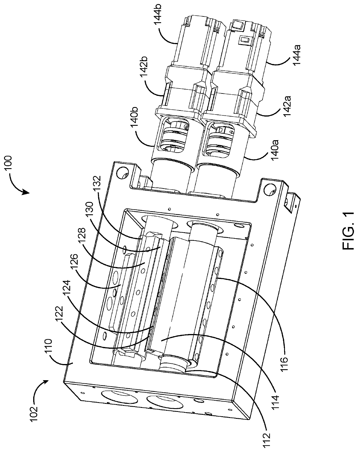
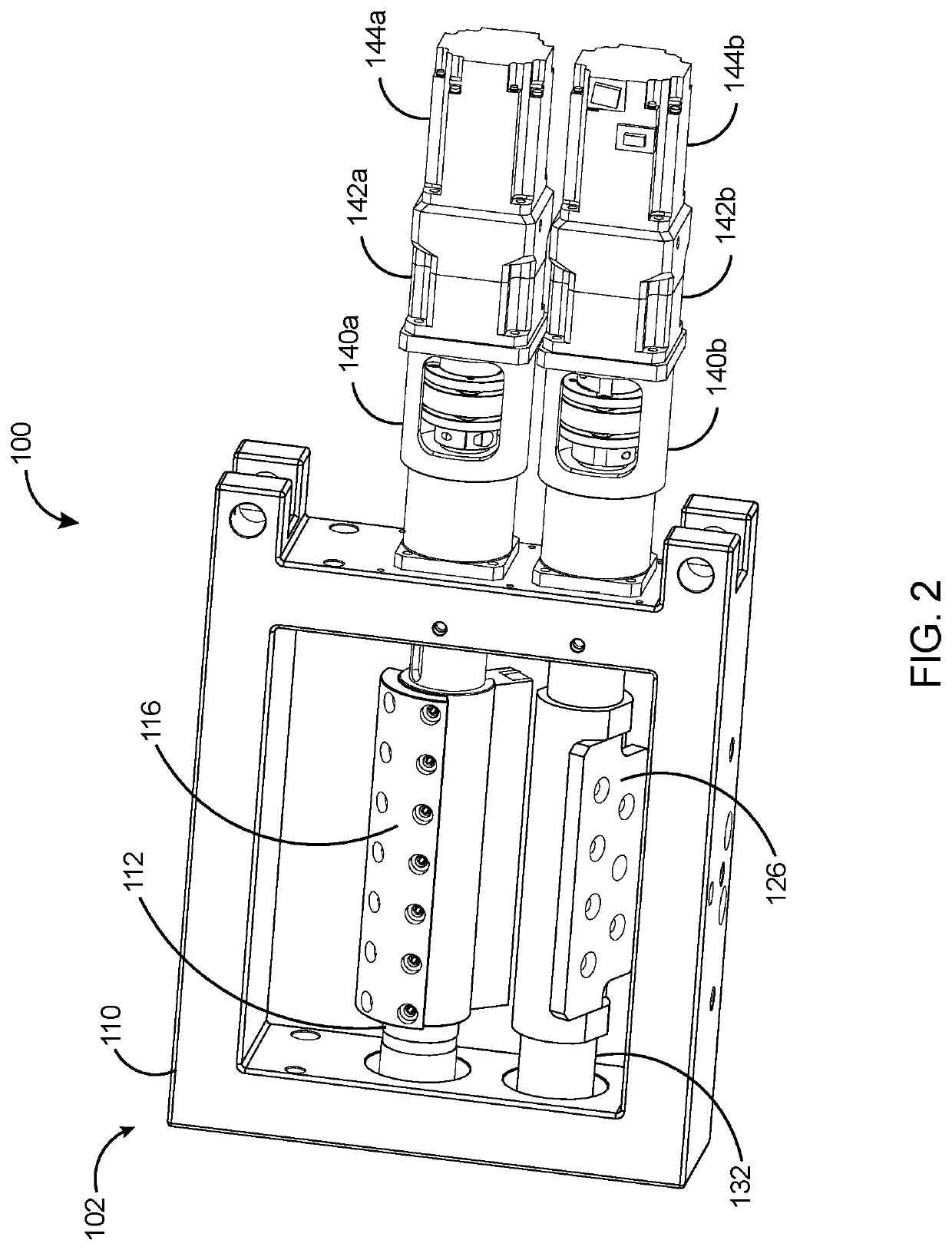
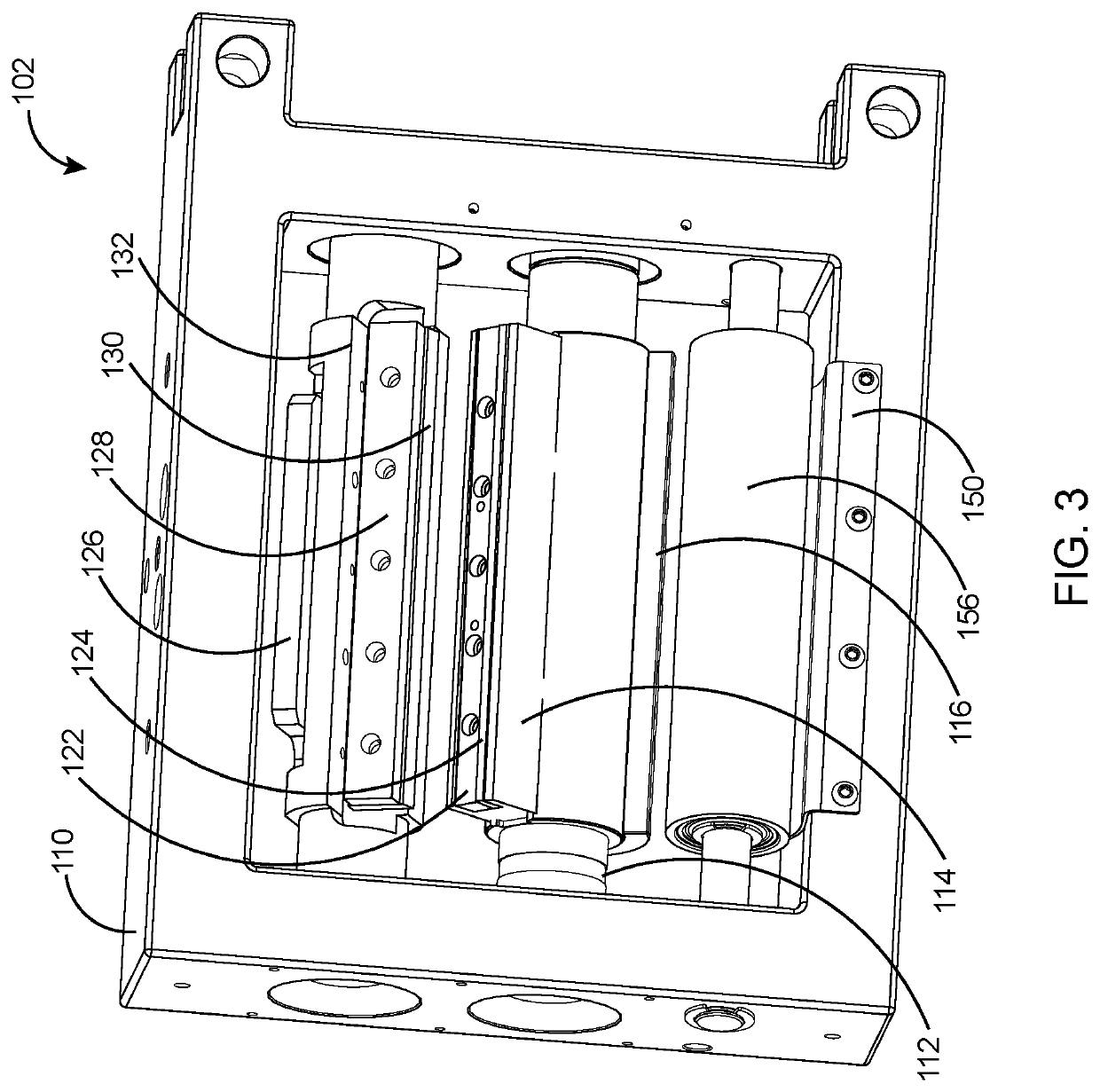
[0012]A second objective of the present invention is to provide a mechanism for producing a label strip of any desired length using a cutter assembly without requiring tooling changes.
[0013]A third objective of the present invention is to provide a method to vary a length of a label strip during cut off from a roll of label web by controlling the distinct speed of rotation of a stationary knife.

Problems solved by technology

Roll fed labeling is recognized to be more economical labeling means, but the complexity of the labeling machine is increased due to the need to control the feed and cutting of the label stock.
The complexity of the labeling procedure has also increased as new labeling materials are developed.
Moreover, the stationary knife is not equipped to cuts on demand and does not ensure desired length of label strips.
This presents the compound problem of having to design and pay for a different cutter roller for each and every label length as well as requiring mechanical disassembly and reassembly of the cutter every time the label size is changed.
There are physical limitations to the maximum and minimum diameters of the cutter roller.
Typically, a change in cutters can take many hours.
With such systems, system optimization is not possible because the optimum speed of the cutter during label transfer is different than the optimum speed for label cut-off.
Hence, this method does not employ adjusting the relative speed of the cutter and knife in order to obtain the labels on demand.
If the relative speed of the cutter is not properly set, the vacuum drum can snap the label segment from the cutter, causing the label to shift.
If the label shifts during transfer, it can result in misalignment of the label on the container.

Method used


Image

  • Systems and methods for cutting label material
  • Systems and methods for cutting label material
  • Systems and methods for cutting label material

Examples


Embodiment Construction

[0030]In the following discussion that addresses a number of embodiments and applications of the present invention, reference is made to the accompanying drawings that form a part hereof, and in which is shown by way of illustrating specific embodiments in which the invention may be practiced. It is to be understood that other embodiments may be utilized and changes may be made without departing from the scope of the present invention.

[0031]Various inventive features are described below that can each be used independently of one another or in combination with other features. However, any single inventive feature may not address any of the problems discussed above or only address one of the problems discussed above. Further, one or more of the problems discussed above may not be fully addressed by any of the features described below. The invention will now be described with reference to the accompanying drawing which does not limit the scope and the ambit of the invention. In the fol...


PUM

PropertyMeasurementUnit
speedaaaaaaaaaa
lengthaaaaaaaaaa
tensionaaaaaaaaaa

Abstract

The present invention is an apparatus and method for cutting individual label strips from a roll of label web utilizing a cutter assembly. A label cutter comprises a cutter assembly for continuously and independently controlling the rotational speeds of a rotating cutter shaft, a stationary shaft, and a label feed roller is provided. The length of the label strip is controlled by the distinct speed of rotation of a stationary knife, the stationary knife is rotatably coupled to the stationary shaft. At least one cutter blade is operatively associated to the rotating cutter shaft for cutting the label web. The stationary knife rotates with a speed of rotation different from the speed of rotation of the cutter blade to produce longer or shorter label length strips. The frequency at which the cutter blade meets the stationary knife is inversely related to the length of the label strip that is produced during cut off.

Description

BACKGROUND OF THE DISCLOSURETechnical Field of the Disclosure[0001]This invention relates to label machines, and more particularly to an improved and adjustable mechanism for accurately cutting label strips into labels of varying lengths.Description of the Related Art[0002]A label is a strip of material attached to an object that is marked with information relevant to and for differentiating an object. The most common form of label is that of a flexible material such as paper or imprintable plastic film that is coated on a first side with an adhesive backing material and on a second side bears indicia relating to the object. Labeling systems are used in a wide variety of manufacturing operations to apply labels on a product, and more specifically, labeling machines are used to apply the label to a container for identification and / or aesthetic reasons. A labeling machine can rapidly change the size of labels cut from a web of labels to match containers of varying diameters, which are...

Claims


Application Information

Patent Timeline
Patent Type & Authority Patents(United States)
IPC IPC(8): B65C9/18B26D1/40B26D1/38B65C9/42B32B43/00
CPCB65C9/1807B65C9/42B32B43/003B26D1/385B26D1/405B65C2009/1861B26D5/20
Inventor CLAIRE, RANBIR SINGHPIRATLA, VINAY LEELADHARCLAIRE, KARMEN
Owner ELUM INC
Why Eureka
Try Eureka