Elevator gearless traction machine construction

a technology of gearless traction and lift, which is applied in the direction of elevators, hoisting equipment, transportation and packaging, etc., can solve the problems of high cost, unflexible construction, and often interfering with the bedplate of the lift, so as to reduce the overall cost of the machine and achieve maximum flexibility of the sheave diameter and sheave width

Inactive Publication Date: 2006-07-13
MAGIL CORP
View PDF5 Cites 24 Cited by
  • Summary
  • Abstract
  • Description
  • Claims
  • Application Information

AI Technical Summary

Benefits of technology

[0006] The present invention is an improved and versatile elevator machine construction allowing maximum flexibility for sheave diameters and sheave width while reducing the overall cost of the machine.
[0010] The plurality of connecting rods may be repositioned into alternate holes in the first and second frame members to accommodate sheaves of various diameters while preventing interference between the elevator car suspension and the connecting rods. Additionally, the length of the connecting rods may be varied to accommodate sheaves of various widths.

Problems solved by technology

The problem inherent to this design is that the ropes 12 often interfere with the bedplate 26 when the diameter of the sheave 10 changes.
Therefore, the construction described above is not flexible because certain sheave diameters are prohibited or require a specific steel structure in order to be implemented.
The bedplate steel structure 26 is generally a massive welded steel assembly, making this change expensive and undesirable.
Another problem is that the dimensioning of the lower steel structure also needs to be changed to accommodate sheaves of various widths.
However, this arrangement produces a large bending moment applied on the sheave.
Therefore, the main structure needs to be very massive in order to limit deflections and stresses, leading to increased cost.
In addition, a major disadvantage of such external rotor construction is that the sheave diameter is dependent of the motor diameter, thus reducing the flexibility of the machine.

Method used


Image

  • Elevator gearless traction machine construction
  • Elevator gearless traction machine construction
  • Elevator gearless traction machine construction

Examples


Embodiment Construction

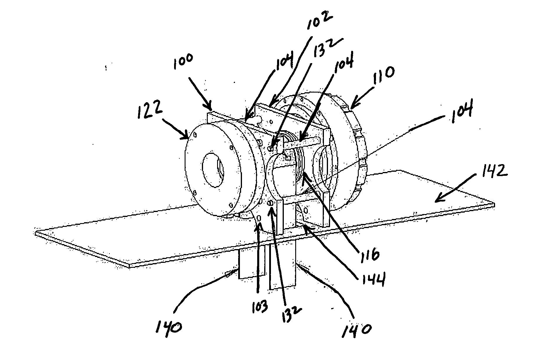
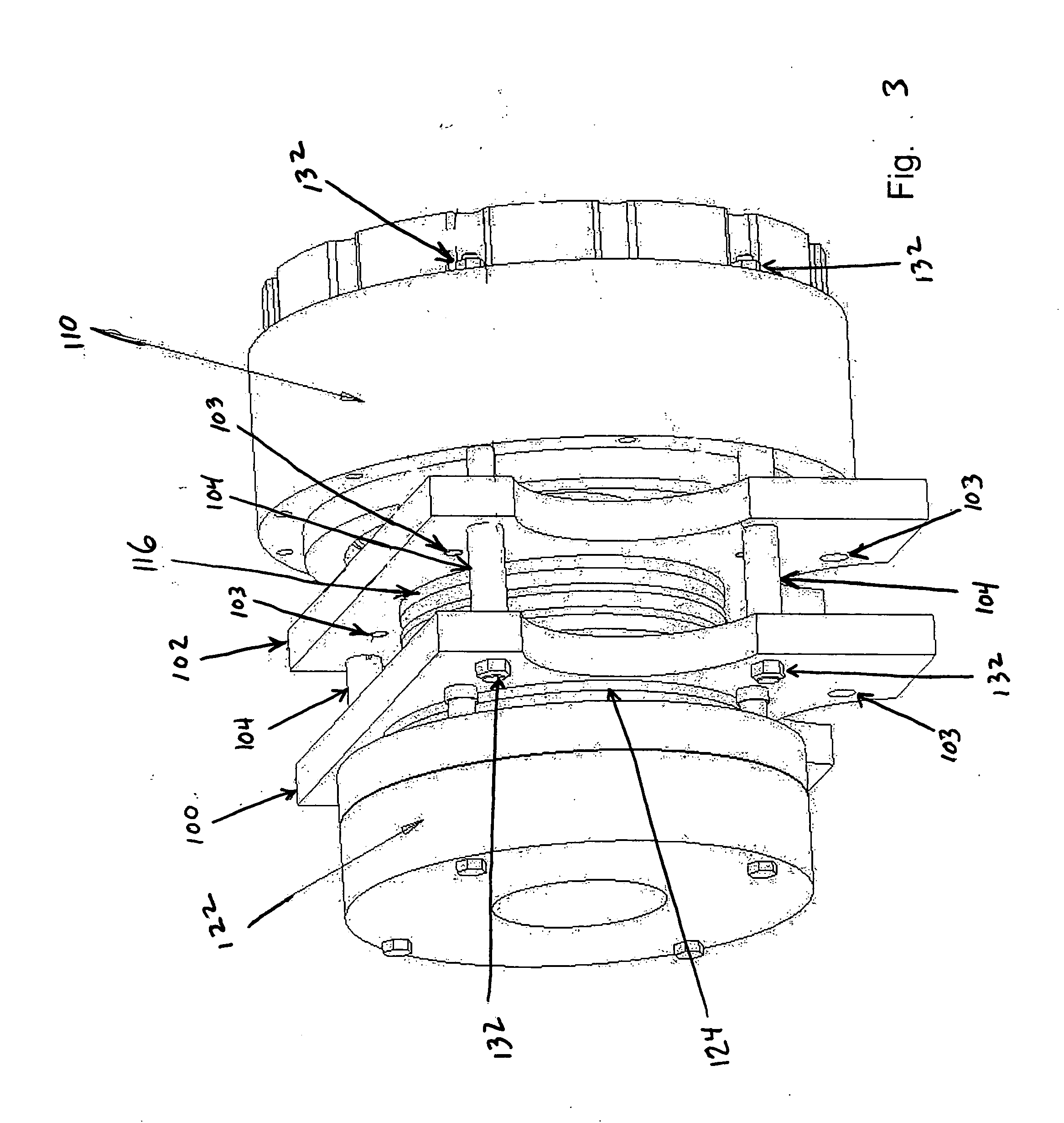
[0021] Referring to FIG. 3 and FIG. 4, two frame members 100, 102, preferably identical, are connected by a plurality of connecting rods 104. Frame members 100, 102 are fabricated from metal such as steel plate of such thickness to provide adequate support for the machine, as will be evident to one skilled in the art. A plurality of holes 103 are drilled, or otherwise machined by means well known in the art, in frame members 100, 102 such that the holes in frame member 100 substantially align with the holes in frame member 102. Provision is also made in frame members 100, 102 for mounting bearings 120, 121 respectively to support a shaft 118. Frame members 100, 102 are then mounted to a plate 142 by means known in the art. In the preferred embodiment, the frame members 100, 102 are mounted to the plate by bolts 146.

[0022] In the preferred embodiment shown in FIG. 3 and FIG. 4, four metal connecting rods 104 are used. The same connecting rods also support the stator 112 of the motor...


PUM


Abstract

A flexible construction for an elevator gearless traction drive machine having a frame that is easily adaptable to traction sheaves of differing widths and diameters while providing the necessary stability for the drive components without an additional structure. The frame is comprised of a pair of frame members joined by a plurality connecting rods. The connecting rods can be mounted in various positions based on the diameter of the sheave to avoid interference between the drive mount and suspension means. Longer or shorter connecting rods may be used based on the width of the sheave.

Description

FIELD OF INVENTION [0001] This invention relates to elevator drives, and in particular to a universal machine frame construction. BACKGROUND OF INVENTION [0002] Gearless traction machines are generally driving a wide range of electric traction elevators. FIG. 1 and FIG. 2 show a typical gearless traction machine construction existing in the art. A traction sheave 10 is driving a plurality of ropes 12 having one end connected to an elevator car and the other end connected to a counterweight. The sheave 10 is rigidly mounted on a shaft 14 which rotates on bearings 16, 18 mounted in pedestals 20, 22. An electric motor 24 is generally attached to one of the pedestals 22 and drives the shaft 14 and the sheave 10. In order for the machine to be rigid, the pedestals 18, 20 are generally mounted on a massive steel structure 26 called a bedplate. Such prior art construction is displayed in Japanese patent JP2003201082, among others. [0003] The problem inherent to this design is that the rope...

Claims


Application Information

Patent Timeline
Patent Type & Authority Applications(United States)
IPC IPC(8): B66B11/08
CPCB66B11/0438
Inventor RENNETAUD, JEAN-MARIE
Owner MAGIL CORP
Why Eureka
Try Eureka