Eureka AIR delivers breakthrough ideas for toughest innovation challenges, trusted by R&D personnel around the world.

Method and assembly for conversion of a standard showerhead to a spray bar

Inactive Publication Date: 2005-06-16
YEISER JOHN O
View PDF23 Cites 25 Cited by
  • Summary
  • Abstract
  • Description
  • Claims
  • Application Information

AI Technical Summary

Benefits of technology

[0012] The present method and assembly are directed to converting a standard showerhead into a combination showerhead and spray bar that can be easily installed without modification of existing house plumbing. In an exemplary embodiment, the spray bar comprises a cylindrical tube approximately {fraction (1 / 2)} to ¾″ (12-20 mm) outer diameter with a series of small bores drilled into the tube parallel with the length of the tube. The tube may be formed from aluminum, steel, hard plastic or other appropriate material. The bores are adapted to project individual horizontal streams of water perpendicular to the surface of the tube. In the exemplary embodiment, a nipple or nozzle is disposed in each bore to assist in focusing the spray and increasing back pressure so that the streams have sufficient pressure to produce a soothing or stimulating effect when they contact the bather's skin. These nozzles may be formed from any suitable polymer, metal, e.g., brass, stainless steel, aluminum, or other appropriate material. When mounted in a vertical orientation, the spray bar produces streams of water that impinge along the length of the user's body, thus providing better body coverage than a standard showerhead that only directs water in a downward direction toward the user's head, neck and / or shoulders. The spray bar is not limited to a linear configuration, but may be formed with alternative shapes, including different curved shapes. The addition of the spray bar of the present invention to an existing showerhead allows the user to select the overhead shower, the spray bar, or a combination of both.
[0013] The spray bar, although labeled a “bar”, is not limited to a linear arrangement of spray nozzles. The spray nozzles may be staggered along a center line, or the spray bar can be configured with curves or bends, such as a “S”, “C” or “U” shape. In the preferred embodiment, the tube has a circular cross-section and is of cylindrical form for ease of manufacture and ease of installation.
[0014] In an alternative embodiment, the spray bar may be configured with a telescoping structure, wherein the length of the bar can be expanded or contracted. This facilitates packaging of the conversion kit for sale, but also permits the user to vary the length of the spray bar during use. In this embodiment, it may be desirable to include flexible seals to minimize leakage between the telescoping segments. Alternatively, the bar can have one or more swivel joints disposed along its length to allow the bar to be folded into smaller segments, which also provide the user the ability to varying the spray pattern from the bar.
[0015] The shower converter assembly is connected to existing plumbing as is present in most standard showers. By removing the existing showerhead from the water outlet pipe and screwing on a 3-way (“T” or “Y” connector), the existing showerhead can be mounted back to one of the two remaining outlets on the 3-way connector and then the spray bar may be attached to the last remaining output connection. This allows the shower conversion kit to be installed in minutes without requiring modification of the existing plumbing or surrounding structures and without sacrificing one showerhead to provide another shower device.
[0016] A first flow control valve may be integrated into the 3-way connector or added between the first outlet of the 3-way connector and the existing showerhead, allowing water flow control and / or differentiation of flow to the spray bar and / or the showerhead. In this embodiment, the user is able to turn off the shower, but keep water flowing to the spray bar. A second flow control valve can be integrated into the second outlet of the 3-way connector or inserted between the second outlet and the spray bar allowing the user to turn off or adjust the pressure from the spray bar independent of the pressure to the showerhead.
[0018] In another embodiment, the spray bar is connected to the 3-way connector using rigid tubing. The tubes are connected to the 3-way connector via a threaded connection, or alternate watertight means. The preferred embodiment utilizes two tubes that are connected to each other via a pivot elbow joint, facilitating re-positioning of the spray bar as desired. The rigid tubing with the pivot elbow joints acts like a pantograph.

Problems solved by technology

Uncoated pipe can rust, which causes further problems, as detailed below.
The traditional shower installation method presents a number of potential problems.
The drop-ear elbows are fairly expensive and, often, will be inadequately secured to the plate behind the wall.
First, the threads of the test pipe often become seized or rusted after a water pressure test is performed, causing excessive stress on the mounting anchors of the elbow as the test pipe is unthreaded.
Secondly, additional stress is applied to the anchors of the elbow as the shower arm is often over tightened in order to orient it in an exact downward direction on the finished or showerhead end.
If the elbow is improperly secured, a variety of problems can ensue, ranging from misalignment of the female threads relative to the hole in the wall, making the shower arm installation difficult or impossible, or kinking and possibly severing the supply pipe.
Even when the 90 degree elbow is properly installed and properly located behind the hole, the test pipe may have been cross threaded or over tightened into the elbow, thus damaging the female threads of the elbow.
The test pipe may then pass the pressure test, but, when it is removed and the shower arm installed into the damaged threads of the elbow, a slow leak can result.
Since the elbow is totally hidden within the wall, the leak can continue for years without being detected, often causing rot and mildew to occur within the wall and / or in the wall bottom plate, with consequent odor and hidden damage.
Also, as there may be rusty, residual water in the test pipe, it may spill onto finished tub / shower surfaces when the test pipe is extracted, permanently staining such surfaces and only remedied by total replacement, with the attendant labor and material expense and delays.
This can result in under tightening or over tightening of the arm to achieve that orientation, which can also result in leaks.
Finally, after a shower arm has been in place for a number of years, it may corrode behind the finished wall and leak or even break off, leaving a threaded portion in the elbow.
Repair of any of these problems necessitates cutting into the finished wall either on the shower side or from behind the shower wall, with the attendant labor, expense and down time associated therewith.
The demolition and repair required for such installations has limited their applications to only those remodeling a shower or building a custom shower.

Method used


Image

  • Method and assembly for conversion of a standard showerhead to a spray bar
  • Method and assembly for conversion of a standard showerhead to a spray bar
  • Method and assembly for conversion of a standard showerhead to a spray bar

Examples


first embodiment

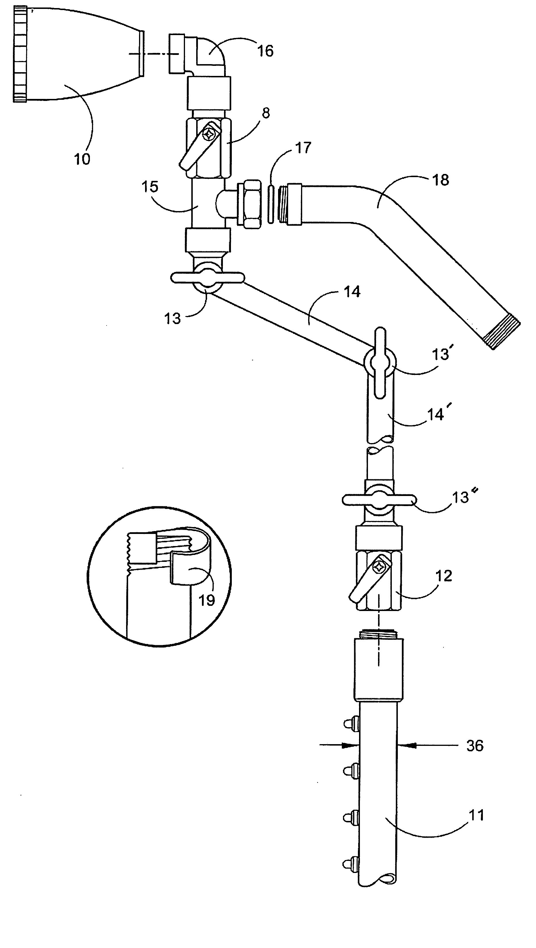
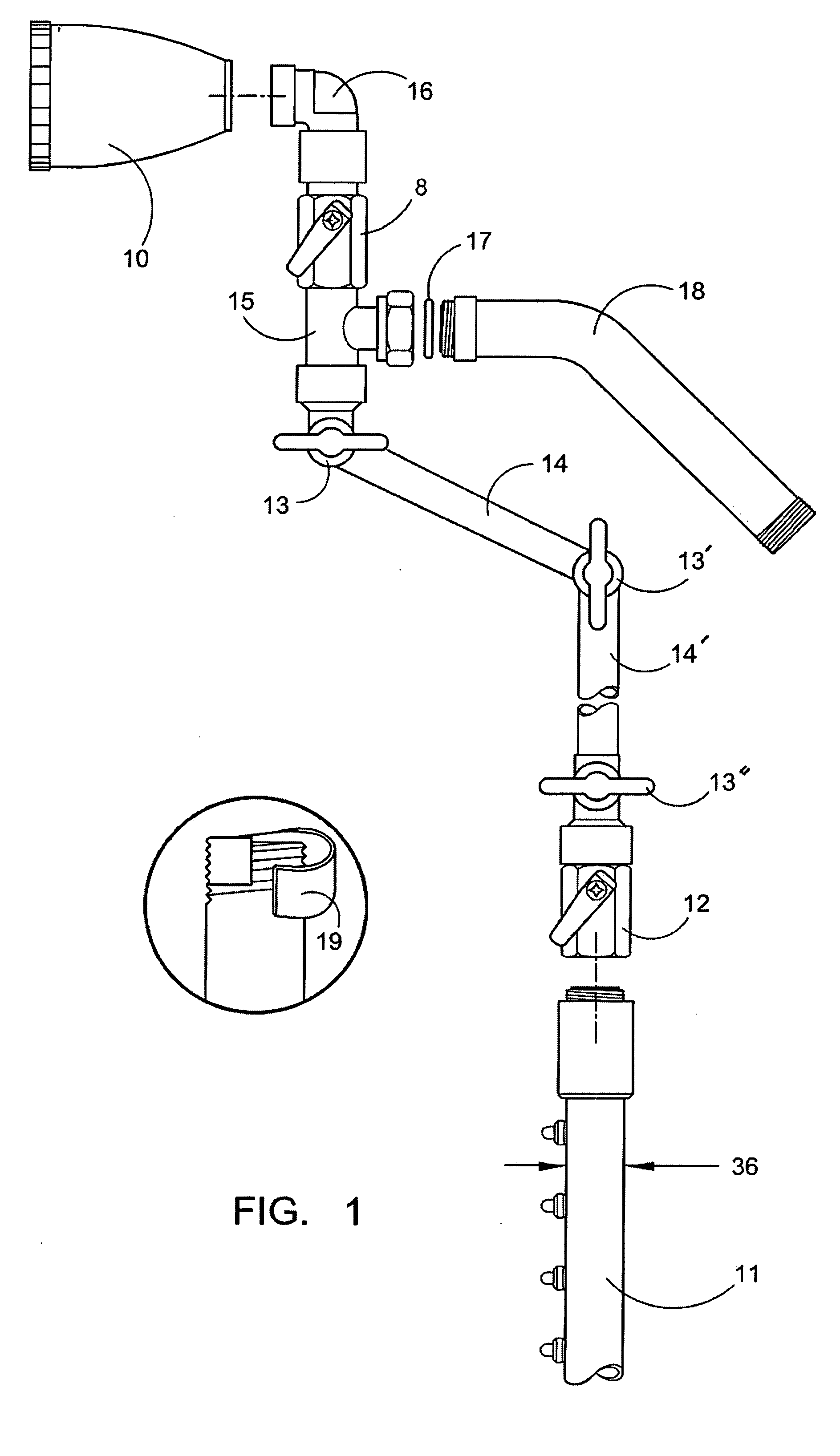
[0032] In a first embodiment, the spa spray bar 11 is mounted on the pre-existing source pipe 18 that extends from the shower wall after removal of the existing showerhead. A standard showerhead 10, such as the one that was previously attached to source pipe 18, is connected through a pipe joint 16 to upper flow control valve 8 to the first outlet of a “T” connector 15. Pipe joint 16 is illustrated as a 90° connection, however, different lengths and angles may be used to achieve the desired orientation for the showerhead 10. Upper flow control valve 8, which is optional, can be adjusted to be fully opened, fully closed or partially open for reduced flow, controls water flow to showerhead 10. For example, if the user wishes to shower without getting his or her hair west, upper flow control valve 8 would be closed, and all of the water would be diverted to spray bar 11. In an alternative embodiment, upper flow control valve 8 can be integrated into the first outlet of “T” connector 15...

second embodiment

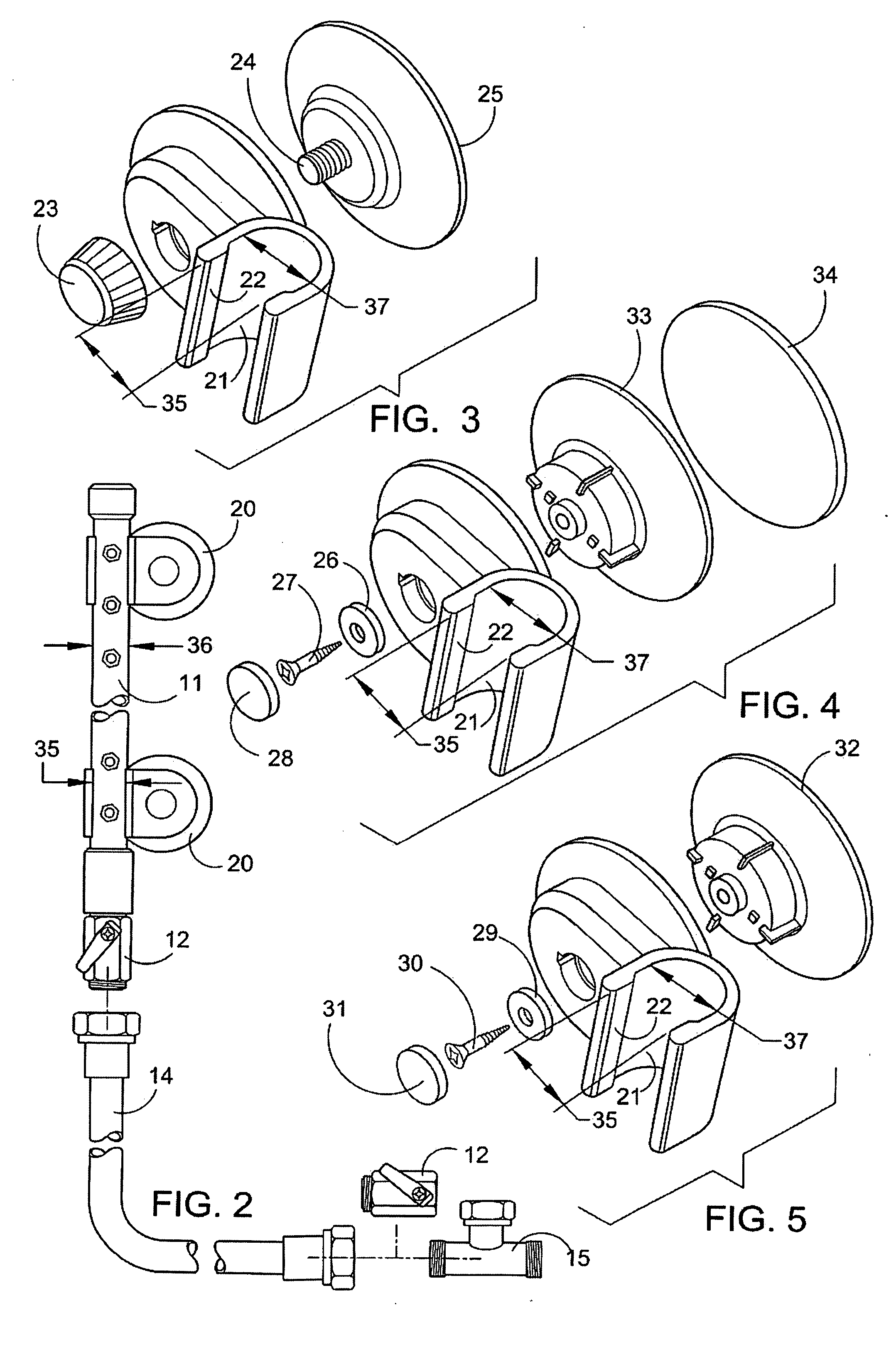
[0033] The present invention is also applicable where the main water supply line is other than a pre-existing shower fixture extending from a shower wall. For example, the invention may be utilized with a standard faucet such as in a tub or with an electrically-heated shower unit. As shown in FIG. 2, the second embodiment includes “T” connector 15, which is connected through first flow control valve 8 which is connected to the connector pipe 14, which may be either flexible or solid tubing. Note that first flow control valve 8 is optional and should not be used with electrically-heated shower units. Connector pipe 14 is connected to optional second flow control valve 12, which is connected to the spray bar 11. The spray bar 11 is affixed to a vertical surface, which can be a shower wall, the wall next to a tub, or to the side of the tub, by one or more mounting brackets 20. While vertical orientation may be preferable for use in a shower, the spray bar 11 need not be mounted in a ve...


PUM


Abstract

The method and assembly are provided for converting a standard showerhead into a combination showerhead and spa spray bar that can be easily installed without modification of existing house plumbing. The spray bar comprises a cylindrical tube with a series of small bores adapted to project individual streams of water perpendicular to the surface of the tube with sufficient pressure to produce a soothing or stimulating effect when they contact the bather's skin. After removal of the existing showerhead, a 3-way connector is connected to the existing water source for directing water to both the showerhead and the spray bar. Flow control valves permit selection one or both of the showerhead and spray bar. The spray bar is attached to a vertical surface located near the bathing position so that multiple water streams are projected towards the user's bathing position.

Description

CROSS-REFERENCE TO RELATED APPLICATIONS [0001] This application is the utility filing of U.S. provisional patent application Ser. No. 60 / 511,184, filed Oct. 14, 2003, which is incorporated herein by reference in its entirety.STATEMENT REGARDING FEDERALLY SPONSORED RESEARCH OR DEVELOPMENT [0002] None. BACKGROUND OF THE INVENTION [0003] Shower installations have traditionally been accomplished by extending a vertical pipe or tube upward from a shower tap to shower height where it is connected to a drop ear 90 degree elbow fitting with {fraction (1 / 2)} inch female N.P.T. (“National Pipe Thread”) threads which faces toward the shower room ready to receive a male threaded shower arm in the final stage of construction, connecting the elbow to a showerhead. The elbow is nailed or screwed securely to a plate positioned within a stud wall which will be closed off with the finished wall. A length of threaded test pipe is then threaded into the elbow. The material used for the test pipe is oft...

Claims


Application Information

Patent Timeline
IPC IPC(8): B05B1/20B05B15/06E03C1/06
CPCB05B1/205E03C2201/30E03C1/06B05B15/064B05B15/628
Inventor YEISER, JOHN O.
Owner YEISER JOHN O
Why Eureka
Eureka Blog
Learn More