
Grease tool for repacking dual angular contact bearing with grease, and method of using same

a technology of grease and angular contact bearing, which is applied in the direction of mechanical equipment, lubricant transfer, transportation and packaging, etc., can solve the problems of reducing the possibility of outside contaminants entering the bearing, premature failure of the bearing, and scratching the bearing surface, so as to facilitate the supply of grease, facilitate cleaning, and facilitate disassembly

Active Publication Date: 2020-06-02
PETIT DENIS
View PDF20 Cites 2 Cited by
  • Summary
  • Abstract
  • Description
  • Claims
  • Application Information

AI Technical Summary

Benefits of technology

The present invention is related to a grease tool for greasing wheel bearings. The tool has a cylindrical hub with a flange for easy removal, and a grease fitting for supplying grease to the wheel bearing. O-rings are placed on the hub to form seals with the inner race of the bearing. A grease dispenser is connected to the fitting to transfer grease from the tool to the bearing. The tool is designed to facilitate easy removal of the grease tool and repacking of the wheel bearing with grease. The technical effects include improved efficiency and ease of use in greasing wheel bearings.

Problems solved by technology

A conventional grease tool allows grease to be inserted and displace any air pockets or other contaminants located within a bearing chamber defined by the bearing, thereby greatly reducing the possibility of outside contaminants entering the bearing and causing premature failure of the bearing.
Moreover, they are generally not easy to insert, typically result in direct metal to metal contact, and rely on a body, a cap or a cover, and a threaded device to fasten the grease tool components to the bearing which runs the risk of scratching the bearing surface and possibly rendering the bearing unusable.
In some instances, the two sides which are assembled together get stuck to the bearing and, thereafter, require forcible removal of the grease tool which can lead to damage to the bearing or possibly the housing.

Method used


Image

  • Grease tool for repacking dual angular contact bearing with grease, and method of using same
  • Grease tool for repacking dual angular contact bearing with grease, and method of using same
  • Grease tool for repacking dual angular contact bearing with grease, and method of using same

Examples


Embodiment Construction

[0036]The present invention will be understood by reference to the following detailed description, which should be read in conjunction with the appended drawings. It is to be appreciated that the following detailed description of various embodiments is by way of example only and is not meant to limit, in any way, the scope of the present invention.

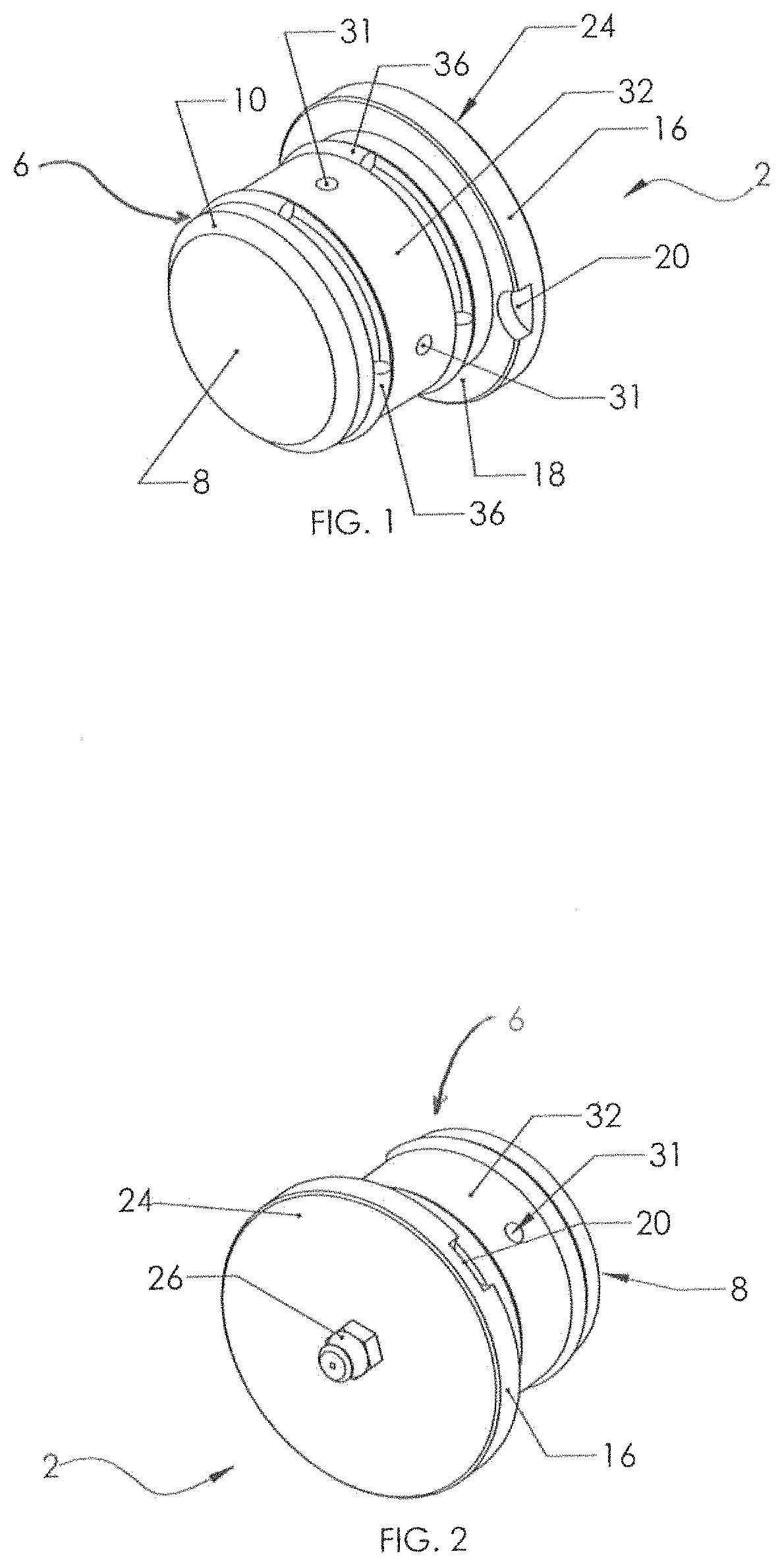
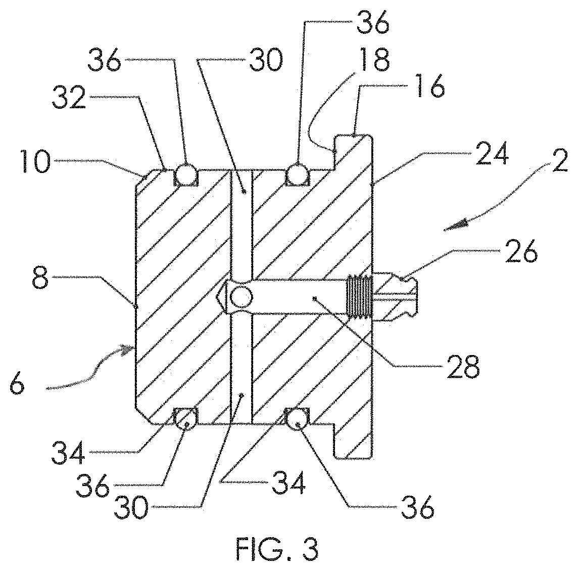
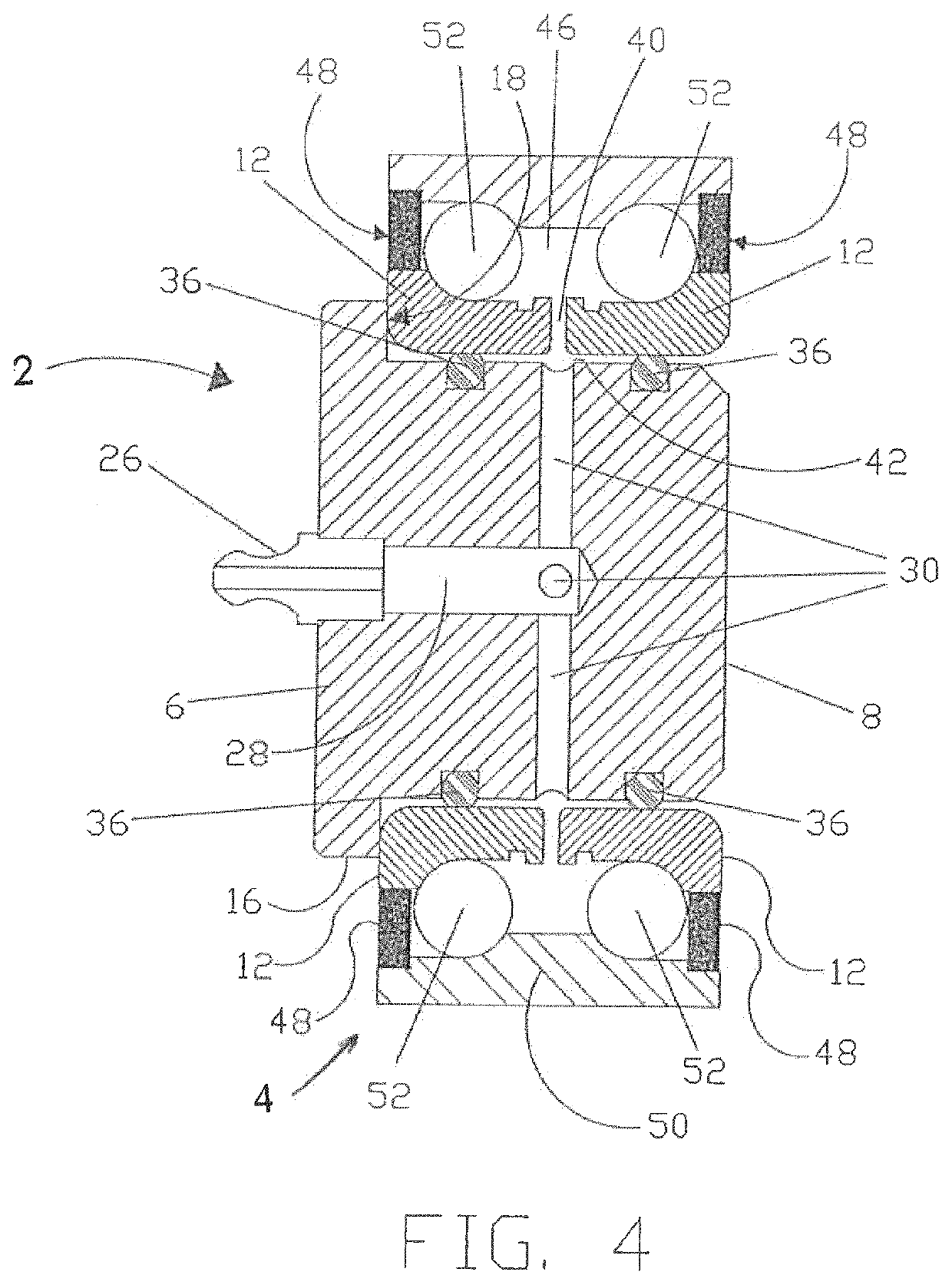
[0037]Turning now to FIGS. 1-4, a brief description concerning the various components of the grease tool 2, according to the present invention, will now be briefly discussed. Thereafter, use of the grease tool 2 to grease a conventional wheel bearing, such as a dual angular contact bearing 4, will then be described. In the following description, the term dual angular contact bearing 4 will be utilized while it is to be appreciated that the present invention is applicable to a variety of different wheel bearings, including dual angular contact bearings.

[0038]As shown in FIGS. 1-4, the grease tool 2 generally comprises an elongate solid cyli...


PUM


Abstract

A grease tool and method for greasing a dual angular contact bearing where the grease tool is fabricated from a single unitary piece of material. The grease tool comprises a cylindrical hub, a flange supported adjacent only one end of the cylindrical hub, and a grease fitting attached to the grease tool to facilitate a supply of grease thereto. During use, a pair of spaced apart O-rings, accommodated by an exterior surface of the cylindrical hub, form a pair of grease seals with an inwardly facing surface of an inner race of the dual angular contact bearing. A supply passage conveys the supplied grease from the grease fitting to a grease outlet(s) located in an exterior cylindrical surface of the grease tool, between the pair of O-rings, for conveyance of the supplied grease radially to the inner race of the dual angular contact bearing and facilitate repacking thereof.

Description

CROSS REFERENCE TO RELATED APPLICATIONS AND PRIORITY CLAIM[0001]This application claims the benefit of U.S. Provisional Patent Application No. 62,355,636, filed on Jun. 28, 2016, which is herein incorporated by reference in its entirety.FIELD OF THE INVENTION[0002]The present invention relates to a grease tool which facilitates supplying grease to an inner race of a wheel bearing, such as a dual angular contact bearing, in order to replenish the supply of grease which is typically required for sufficient lubrication of the ball bearings contained therein.BACKGROUND OF THE INVENTION[0003]A conventional grease tool allows grease to be inserted and displace any air pockets or other contaminants located within a bearing chamber defined by the bearing, thereby greatly reducing the possibility of outside contaminants entering the bearing and causing premature failure of the bearing. Prior art methods and techniques typically utilize a tool that requires access to both sides of the wheel b...

Claims


Application Information

Patent Timeline
Patent Type & Authority Patents(United States)
IPC IPC(8): F16N37/00F16C33/66F16C19/18F16N21/02
CPCF16C33/6622F16N21/02F16N37/003F16C33/6603F16C2326/02F16C19/184
Inventor PETIT, DENIS
Owner PETIT DENIS
Learn More