Method for increasing vacuum production for a vehicle

a technology for vehicles and vacuum production, applied in the direction of machines/engines, electric control, combustion air/fuel air treatment, etc., can solve the problems of unable to provide the desired amount of vacuum at higher altitudes, and achieve the effect of reducing engine emissions, sufficient vacuum, and preserving fuel

Active Publication Date: 2020-06-09
FORD GLOBAL TECH LLC
View PDF22 Cites 0 Cited by
  • Summary
  • Abstract
  • Description
  • Claims
  • Application Information

AI Technical Summary

Benefits of technology

[0002]Vehicle engine displacement may be reduced to conserve fuel and reduce engine emissions. A driver may request similar torque amounts from a small engine as from a larger engine under similar operating conditions. The smaller engine may operate at a higher intake manifold pressure to produce a same amount of torque produced by a larger engine operating at a lower intake manifold pressure. As a result, the larger engine may operate with intake manifold pressure that is lower than atmospheric pressure more frequently than the smaller engine during similar operating conditions. The lower intake manifold pressures, or higher intake vacuum, produced by the larger engine may allow the larger engine to provide more vacuum to vehicle systems that operate with vacuum (e.g., brakes, HVAC vents, etc.). The smaller engine may produce sufficient vacuum at higher barometric pressures (e.g., at lower altitudes), but it may struggle to provide a desired amount of vacuum at higher altitudes where less oxygen concentration may be available.
[0003]The inventors herein have recognized the above-mentioned disadvantages and have developed a method for operating an engine, comprising: operating an engine at idle speed with a homogeneous air-fuel mixture; and richening the homogeneous air-fuel mixture and reducing an engine air flow amount to maintain the engine at idle speed in response to a request for vacuum.
[0004]By richening an air-fuel ratio provided to an engine in response to a request for vacuum, it may be possible to provide the technical result of generating additional vacuum within an engine during operating conditions that may not be conducive to generating vacuum. For example, if an engine is idling at a higher altitude and a request for vacuum is provided in response to a low level of stored vacuum, the engine air-fuel ratio may be richened so that the engine provides the same torque as before the engine air-fuel ratio was richened with a lower engine air flow amount. By lowering the amount of air flowing through the engine, the engine may increase a vacuum level of an intake manifold so that the stored vacuum amount may be increased.
[0005]The present description may provide several advantages. Specifically, the approach may allow an engine to produce additional vacuum at higher altitudes. Further, the approach may provide additional vacuum without increasing system cost. Additionally, the approach may increase vacuum production without increasing engine emissions.

Problems solved by technology

The smaller engine may produce sufficient vacuum at higher barometric pressures (e.g., at lower altitudes), but it may struggle to provide a desired amount of vacuum at higher altitudes where less oxygen concentration may be available.

Method used


Image

  • Method for increasing vacuum production for a vehicle
  • Method for increasing vacuum production for a vehicle
  • Method for increasing vacuum production for a vehicle

Examples


Embodiment Construction

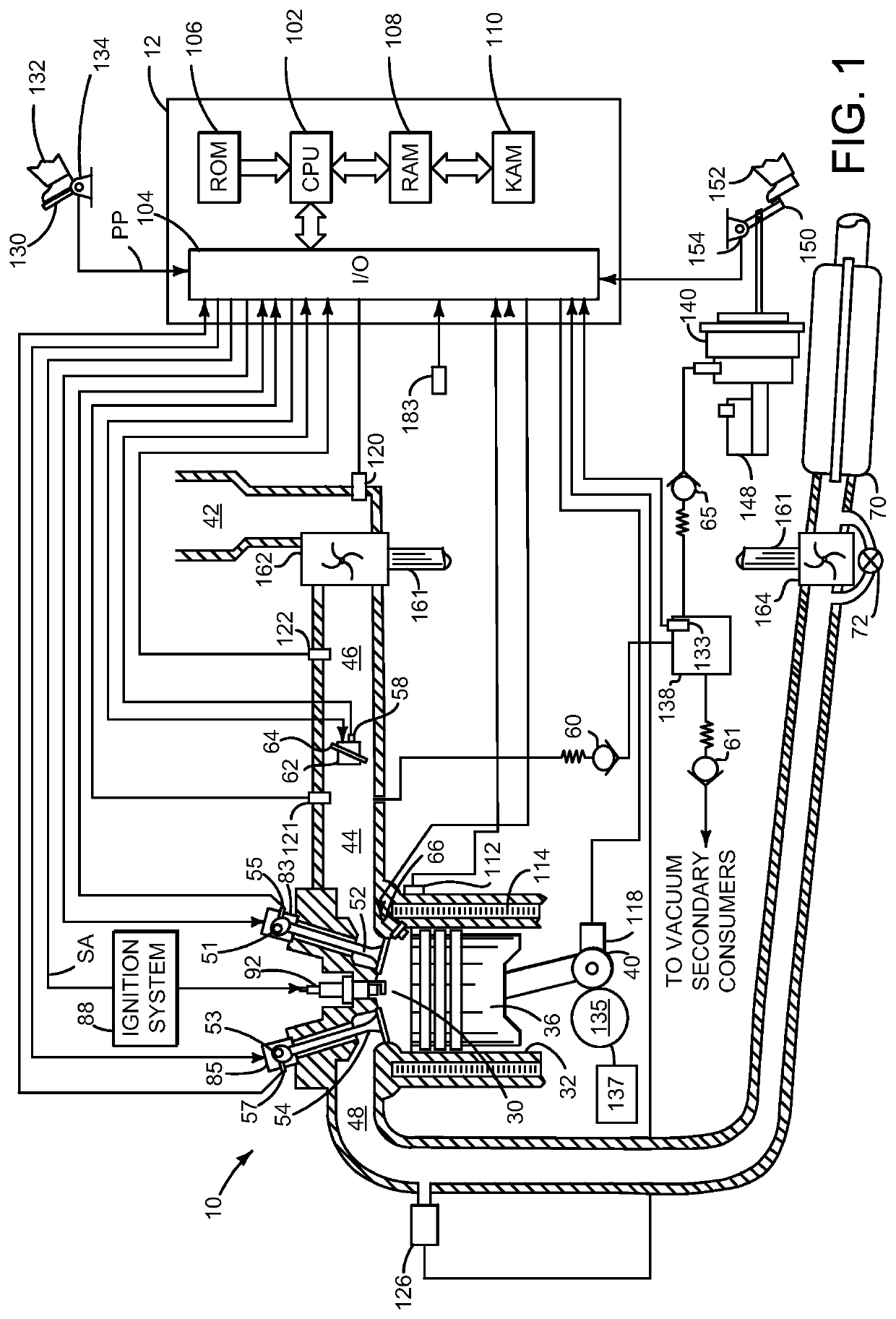
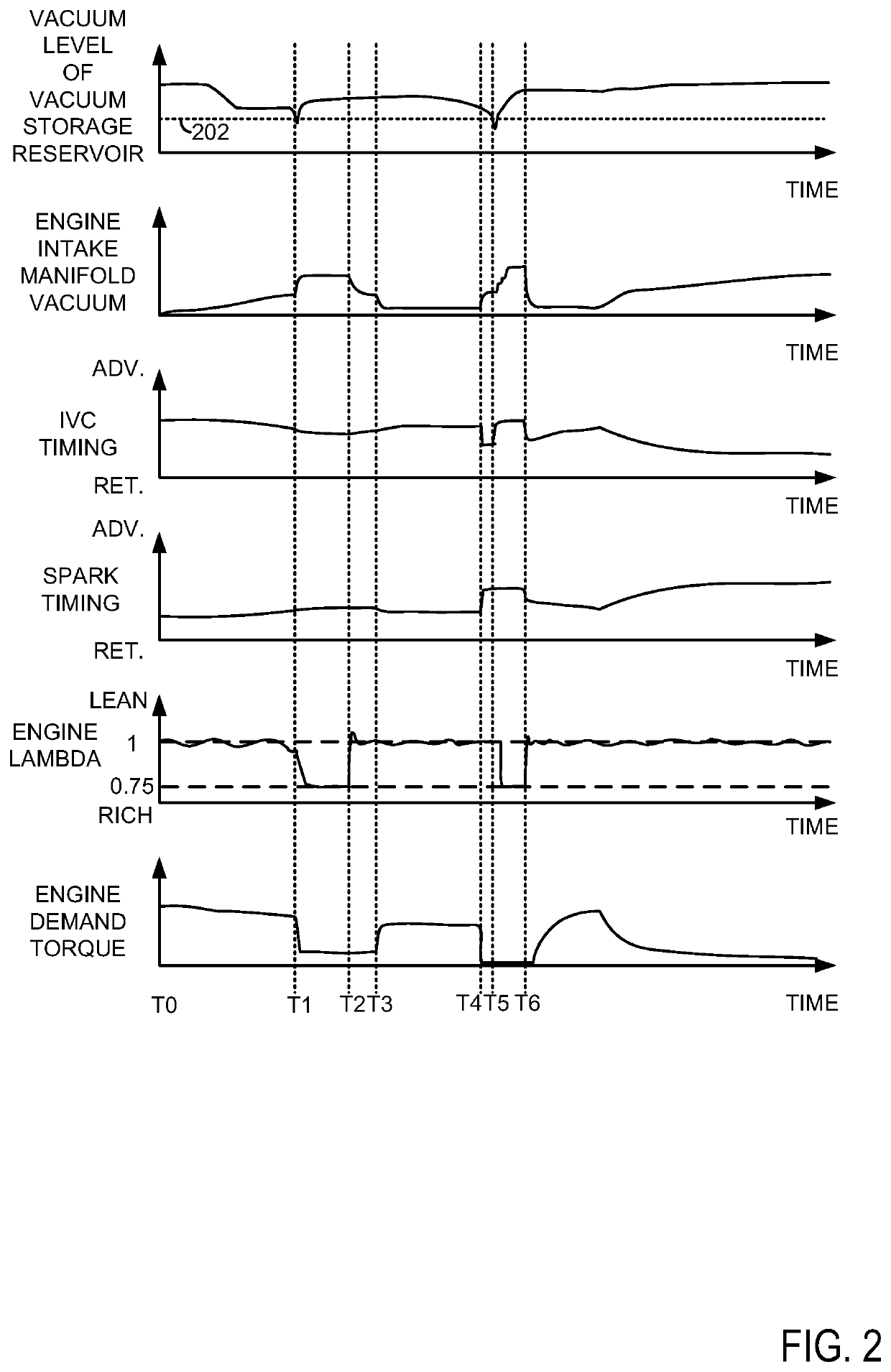
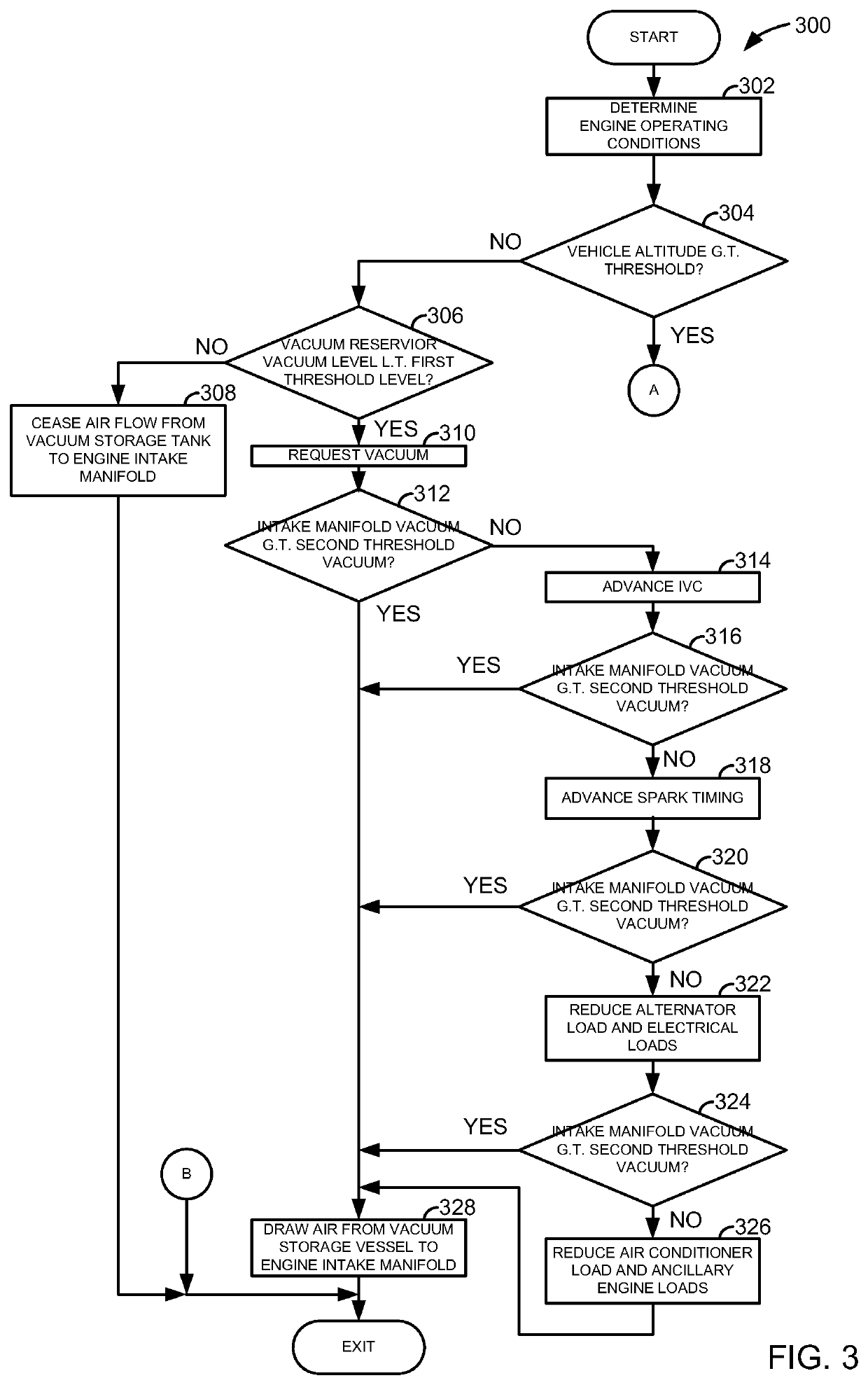
[0012]The present description is related to providing vacuum for vacuum consumers of a vehicle. In one non-limiting example, an engine as illustrated in FIG. 1 may be a source for generating vacuum used throughout the vehicle. FIG. 2 shows an example engine operating sequence according to the method of FIGS. 3 and 4. Vacuum may be provided to vacuum consumers of a vehicle according to the method of FIGS. 3 and 4.

[0013]Referring to FIG. 1, internal combustion engine 10, comprising a plurality of cylinders, one cylinder of which is shown in FIG. 1, is controlled by electronic engine controller 12. Engine 10 includes combustion chamber 30 and cylinder walls 32 with piston 36 positioned therein and connected to crankshaft 40. Combustion chamber 30 is shown communicating with intake manifold 44 and exhaust manifold 48 via respective intake valve 52 and exhaust valve 54. Each intake and exhaust valve may be operated by an intake cam 51 and an exhaust cam 53. The position of intake cam 51 ...


PUM


Abstract

Methods and systems for providing vacuum to a vehicle are described. In one example, a method adjusts an engine air-fuel ratio in response to provide additional vacuum to the vehicle.

Description

FIELD[0001]The present description relates to methods and systems for operating an engine that produces vacuum for a vehicle. The methods and systems may be particularly useful for engines that are operated at higher altitudes.BACKGROUND AND SUMMARY[0002]Vehicle engine displacement may be reduced to conserve fuel and reduce engine emissions. A driver may request similar torque amounts from a small engine as from a larger engine under similar operating conditions. The smaller engine may operate at a higher intake manifold pressure to produce a same amount of torque produced by a larger engine operating at a lower intake manifold pressure. As a result, the larger engine may operate with intake manifold pressure that is lower than atmospheric pressure more frequently than the smaller engine during similar operating conditions. The lower intake manifold pressures, or higher intake vacuum, produced by the larger engine may allow the larger engine to provide more vacuum to vehicle systems...

Claims


Application Information

Patent Timeline
Patent Type & Authority Patents(United States)
IPC IPC(8): F02M3/00F02D41/30F02M35/10F02D41/08F02D41/14F02D13/02F02D9/02
CPCF02M35/10229F02D41/3017F02M3/005F02D13/0207F02D41/08F02D41/1475F02D13/0265F02D2250/41F02D2009/024F02D2200/703Y02T10/18Y02T10/12
Inventor PURSIFULL, ROSS DYKSTRACUNNINGHAM, RALPH WAYNE
Owner FORD GLOBAL TECH LLC
Why Eureka
Try Eureka