Imaging lens
a technology of imaging and lens, which is applied in the field of imaging lenses, can solve the problems of inability to obtain excellent optical performance and difficulty in correcting aberrations at the peripheral area, and achieve the effects of low f-number, correcting aberrations, and high resolution
- Summary
- Abstract
- Description
- Claims
- Application Information
AI Technical Summary
Benefits of technology
Problems solved by technology
Method used
Image

Examples
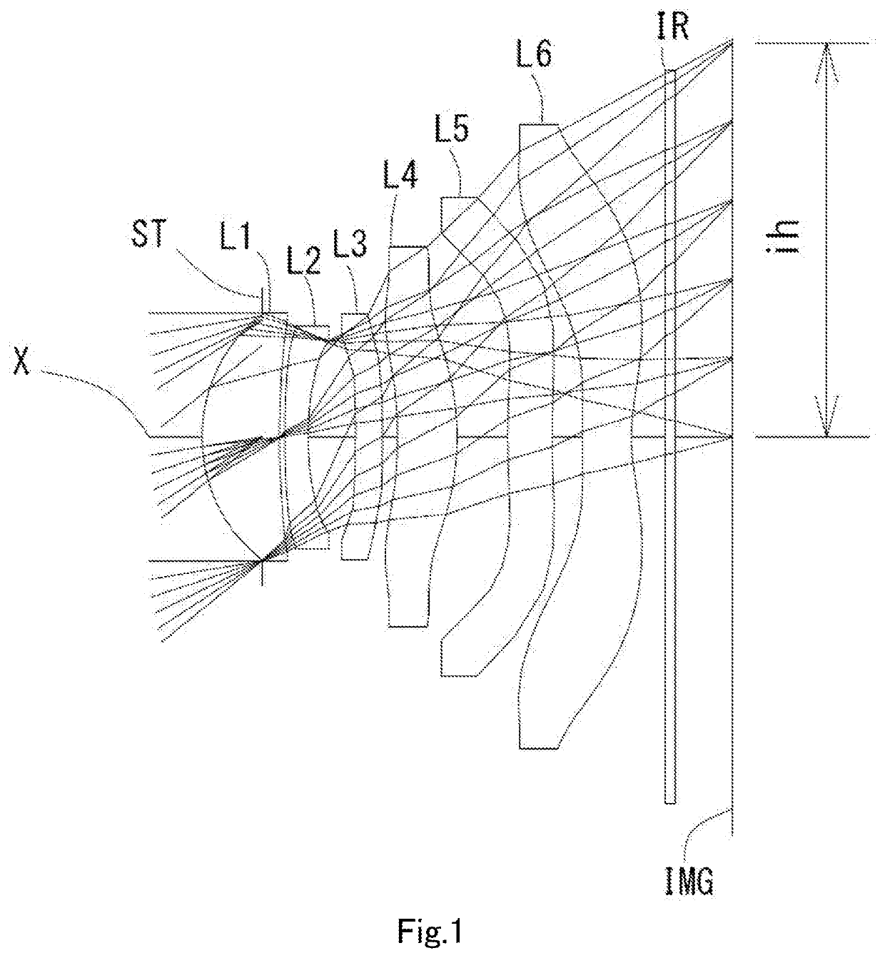
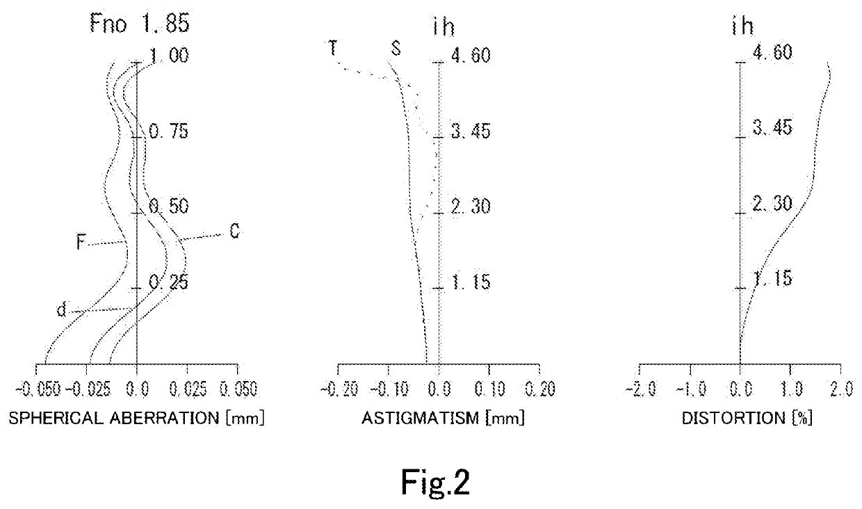
example 1
[0167]The basic lens data is shown below in Table 1.
[0168]
TABLE 1Example 1Unit mmf = 5.57ih = 4.60Fno = 1.85TTL = 6.14ω (°) = 38.9Surface DataSurfaceCurvatureSurfaceRefractiveAbbeNumber iRadius rDistance dIndex NdNumber vd(Object)InfinityInfinity 1 (Stop)Infinity−0.6950 2*1.84980.89981.54455.86 (vd1) 3*11.51840.0640 4*12.24790.27201.66120.37 (vd2) 5*3.97100.5502 6*154.06510.31401.66120.37 (vd3) 7*−199.79720.1754 8*−4.89590.69141.53555.66 (vd4) 9*−3.35810.590310*11.67680.51991.66120.37 (vd5)11*36.92380.351012*14.27360.56961.53555.66 (vd6)13*2.26920.129014Infinity0.11001.51557.0015Infinity0.9450Image PlaneInfinityConstituent Lens DataLensStart SurfaceFocal LengthComposite Focal Length123.920f125.81724−9.011f3415.43636131.697f234−30.8214817.28451025.635612−5.130Aspheric Surface DataSecond SurfaceThird SurfaceFourth SurfaceFifth SurfaceSixth SurfaceSeventh Surfacek0.000000E+000.000000E+000.000000E+000.000000E+000.000000E+000.000000E+00A4−6.559581E−042.559000E−022.284504E−022.682232E−02−...
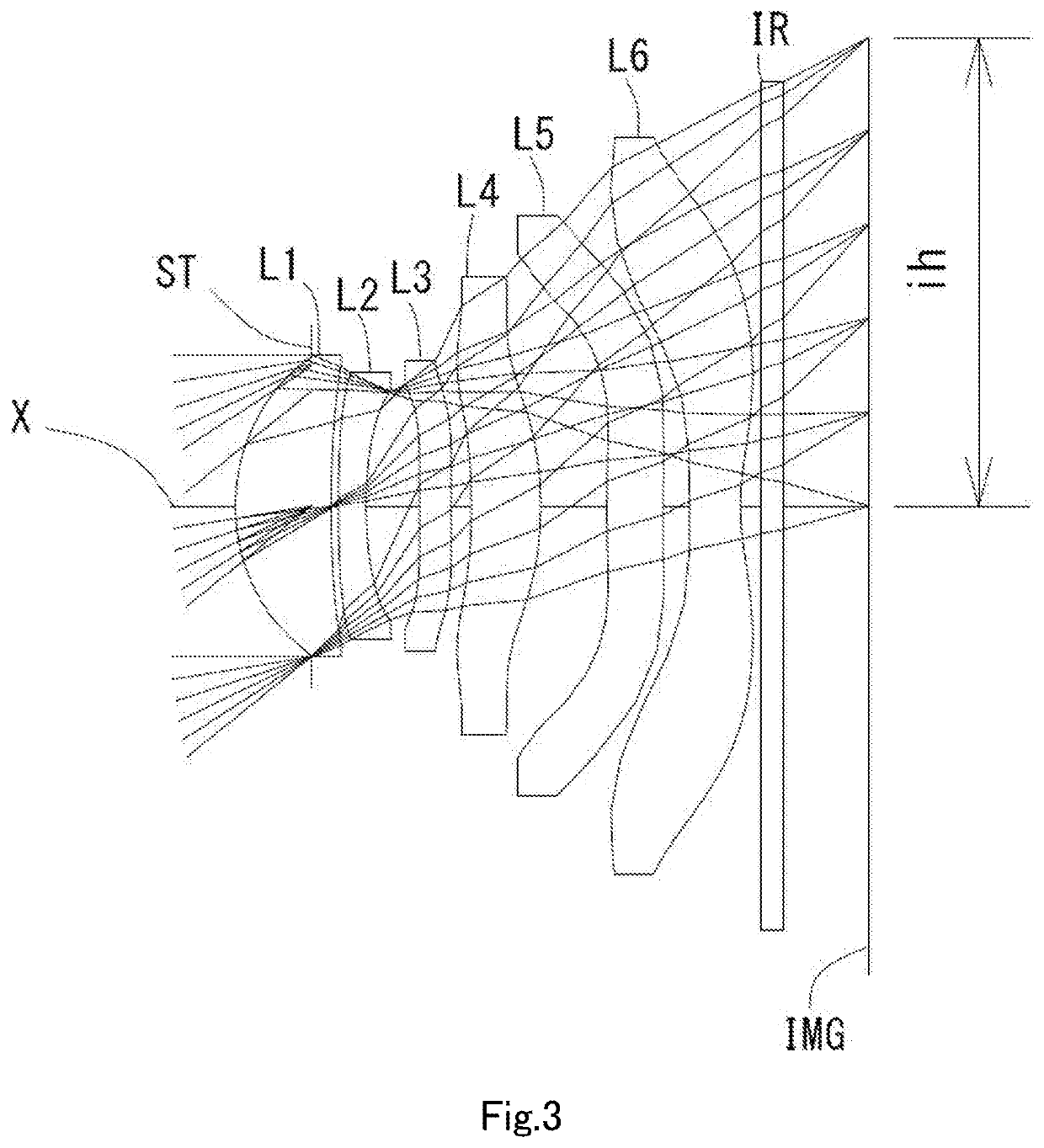
example 2
[0171]The basic lens data is shown below in Table 2.
[0172]
TABLE 2Example 2Unit mmf = 5.55ih = 4.60Fno = 1.85TTL = 6.11ω (°) = 38.9Surface DataSurfaceCurvatureSurfaceRefractiveAbbeNumber iRadius rDistance dIndex NdNumber vd(Object)InfinityInfinity 1 (Stop)Infinity−0.7400 2*1.85720.93591.54455.86 (vd1) 3*11.34040.0734 4*14.57770.27201.66120.37 (vd2) 5*4.22040.5225 6*39.04150.31161.66120.37 (vd3) 7*32.90210.1970 8*−6.39760.67831.53555.66 (vd4) 9*−3.60480.646210*12.09630.55291.66120.37 (vd5)11*−216.44560.258012*87.16040.50101.53555.66 (vd6)13*2.40600.206514Infinity0.21001.51764.2015Infinity0.8163Image PlaneInfinityConstituent Lens DataLensStart SurfaceFocal LengthComposite Focal Length123.943f125.82624−9.085f3414.88736−323.184f234−33.6434814.23651017.355612−4.636Aspheric Surface DataSecond SurfaceThird SurfaceFourth SurfaceFifth SurfaceSixth SurfaceSeventh Surfacek0.000000E+000.000000E+000.000000E+000.000000E+000.000000E+000.000000E+00A4−6.342804E−042.234428E−022.306549E−022.963554E−02−...
example 3
[0175]The basic lens data is shown below in Table 3.
[0176]
TABLE 3Example 3Unit mmf = 5.56ih = 4.60Fno = 1.85TTL = 6.11ω (°) = 38.9Surface DataSurfaceCurvatureSurfaceRefractiveAbbeNumber iRadius rDistance dIndex NdNumber vd(Object)InfinityInfinity 1 (Stop)Infinity−0.7000 2*1.84550.89711.54455.86 (vd1) 3*10.81830.0768 4*13.41550.27201.66120.37 (vd2) 5*4.13910.5373 6*37.38480.31321.66120.37 (vd3) 7*27.89520.1923 8*−6.25730.66061.53555.66 (vd4) 9*−3.60410.671410*10.25530.56001.66120.37 (vd5)11*359.89950.236012*38.88940.50291.53555.66 (vd6)13*2.32100.767714Infinity0.21001.51764.2015Infinity0.2838Image PlaneInfinityConstituent Lens DataLensStart SurfaceFocal LengthComposite Focal Length123.949f125.82824−9.166f3415.95636−168.531f234−29.5044814.62451015.966612−4.638Aspheric Surface DataSecond SurfaceThird SurfaceFourth SurfaceFifth SurfaceSixth SurfaceSeventh Surfacek0.000000E+000.000000E+000.000000E+000.000000E+000.000000E+000.000000E+00A4−4.946121E−042.267080E−022.353818E−023.022076E−02−4...
PUM
 Abstract
Description
Claims
Application Information
 - R&D
- Intellectual Property
- Life Sciences
- Materials
- Tech Scout
- Unparalleled Data Quality
- Higher Quality Content
- 60% Fewer Hallucinations
Browse by: Latest US Patents, China's latest patents, Technical Efficacy Thesaurus, Application Domain, Technology Topic, Popular Technical Reports.
© 2025 PatSnap. All rights reserved.Legal|Privacy policy|Modern Slavery Act Transparency Statement|Sitemap|About US| Contact US: help@patsnap.com