Condenser system for high pressure processing system

a processing system and condenser technology, applied in lighting and heating equipment, supercritical condition processes, cleaning using liquids, etc., can solve the problems of unfavorable high-pressure operation environment, conventional equipment is not equipped to accommodate unique pressure regimes, and conventional equipment cannot be easily retrofitted to accommodate high-pressure operating environments without unnecessary risk of catastrophic apparatus failur

Active Publication Date: 2020-06-16
APPLIED MATERIALS INC
View PDF241 Cites 11 Cited by
  • Summary
  • Abstract
  • Description
  • Claims
  • Application Information

AI Technical Summary

Problems solved by technology

However, conventional apparatus are not equipped to accommodate the unique pressure regimes associated with supercritical fluid processing.
Moreover, conventional apparatus cannot easily be retrofitted to accommodate high pressure operating environments without the unnecessary risk of catastrophic apparatus failure.

Method used


Image

  • Condenser system for high pressure processing system

Examples


Embodiment Construction

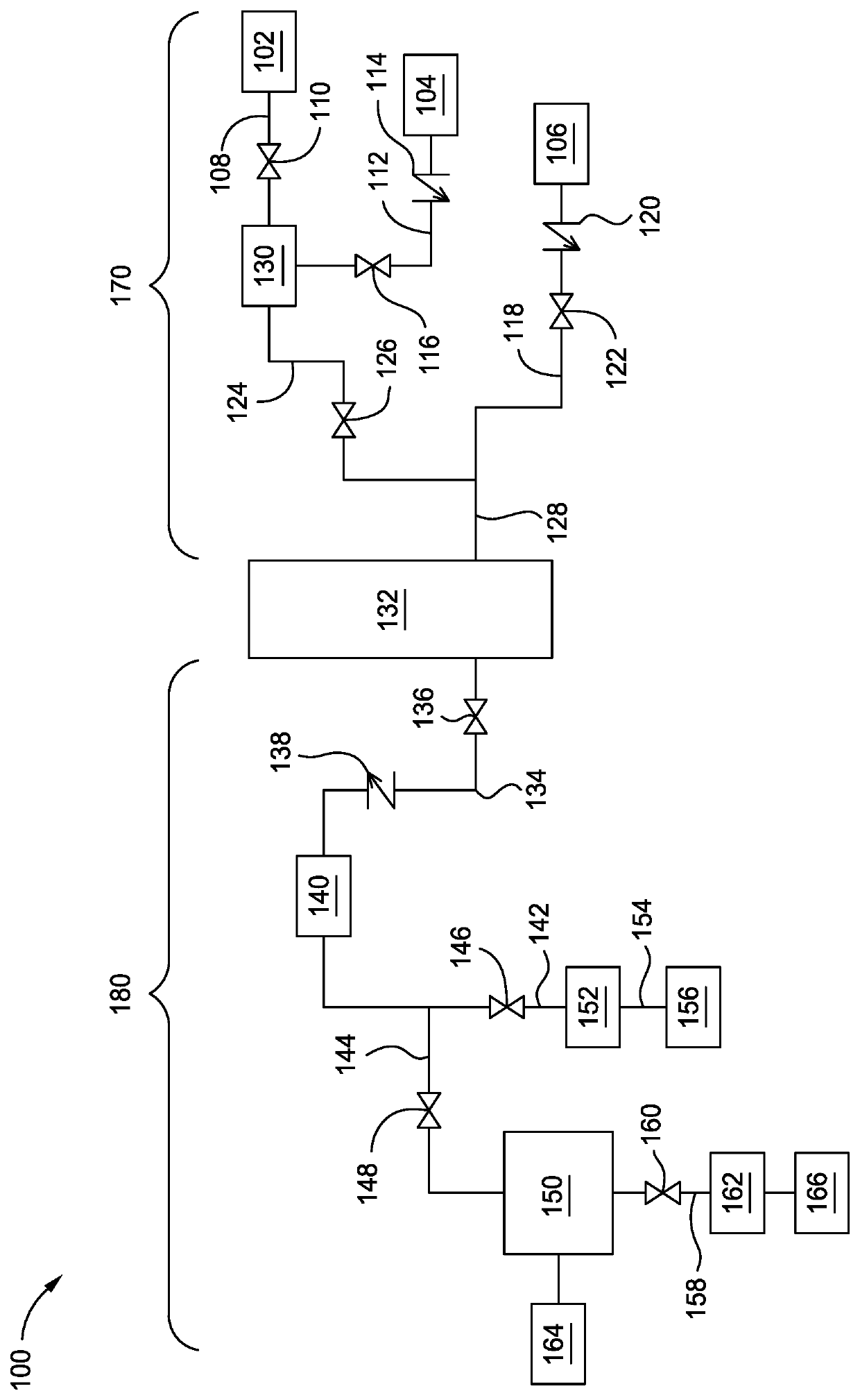
[0011]Embodiments described herein relate to a high pressure processing system with a condenser and methods for utilizing the same. The processing system includes a process chamber, a boiler, a condenser, and one or more heat exchangers. The boiler generates a fluid, such as a vapor or supercritical fluid, and delivers the fluid to the process chamber where a substrate is processed. After processing the substrate, the system is depressurized and the fluid is delivered to the condenser where the fluid is condensed.

[0012]FIG. 1 is a schematic illustration of a high pressure processing system 100 with a condenser150 according to an embodiment described herein. The system 100 includes a process chamber 132, a boiler 130, one or more heat exchangers 140, 152, 162, and the condenser 150. The boiler 130 is disposed in an upstream region 170 from the process chamber 132 and the heat exchangers 140, 152, 162 and condenser 150 are disposed in a downstream region 180 from the process chamber 1...


PUM


Abstract

Embodiments described herein relate to a high pressure processing system with a condenser and methods for utilizing the same. The processing system includes a process chamber, a boiler, a condenser, and one or more heat exchangers. The boiler generates a fluid, such as a vapor or supercritical fluid, and delivers the fluid to the process chamber where a substrate is processed. After processing the substrate, the system is depressurized and the fluid is delivered to the condenser where the fluid is condensed.

Description

CROSS-REFERENCE TO RELATED APPLICATIONS[0001]This application claims benefit of U.S. Provisional Patent Application No. 62 / 587,916, filed Nov. 17, 2017, the entirety of which is hereby incorporated by reference.BACKGROUNDField[0002]Embodiments of the present disclosure generally relate to a substrate processing apparatus. More specifically, embodiments described herein relate to a condenser system for a high pressure processing system.Description of the Related Art[0003]Conventional substrate processing systems often operate at reduced pressures during processing operations. Recent developments in certain processing technology, such as substrate cleaning, utilize high pressure environments compatible with steam or supercritical fluids. However, conventional apparatus are not equipped to accommodate the unique pressure regimes associated with supercritical fluid processing. Moreover, conventional apparatus cannot easily be retrofitted to accommodate high pressure operating environmen...

Claims


Application Information

Patent Timeline
Patent Type & Authority Patents(United States)
IPC IPC(8): H01L21/02H01L21/67B08B3/02F22B29/08F16T1/38
CPCH01L21/02101H01L21/67034F22B29/08F16T1/38B08B3/02B01J3/008B01J3/002B01J2219/00054B01J2219/00162B01J2219/00495
Inventor DELMAS, JEAN
Owner APPLIED MATERIALS INC
Why Eureka
Try Eureka