Rotor for wound-rotor motor and wound-rotor motor having the same

a technology of rotor and motor, which is applied in the direction of dynamo-electric components, dynamo-electric machines, magnetic circuit shapes/forms/construction, etc., can solve the problems of decreasing the magnitude of counter electromotive force, increasing the torque of the motor, and increasing the air gap exponentially. , to achieve the effect of improving the total harmonic distortion

Active Publication Date: 2020-06-16
HL MANDO CORP
View PDF10 Cites 3 Cited by
  • Summary
  • Abstract
  • Description
  • Claims
  • Application Information

AI Technical Summary

Benefits of technology

[0009]The present invention is directed to a rotor for a wound-rotor motor for improving a total harmonic distortion (THD) while a magnitude of a counter electromotive force is constantly maintained, and a wound-rotor motor having the same.

Problems solved by technology

However, in the case of the BSG, since a spatial limitation is big to increase the number of coil windings and an increase in current is limited, there is a problem in that an increase in torque of the motor is limited.
In addition, in the case of a rotor including a plurality of arrays, when an ideal curve, such as a generally known inverse cosine, is applied to the rotor, there is a problem in that an air gap increases exponentially and a magnitude of a counter electromotive force decreases.

Method used


Image

  • Rotor for wound-rotor motor and wound-rotor motor having the same
  • Rotor for wound-rotor motor and wound-rotor motor having the same
  • Rotor for wound-rotor motor and wound-rotor motor having the same

Examples


first modified embodiment

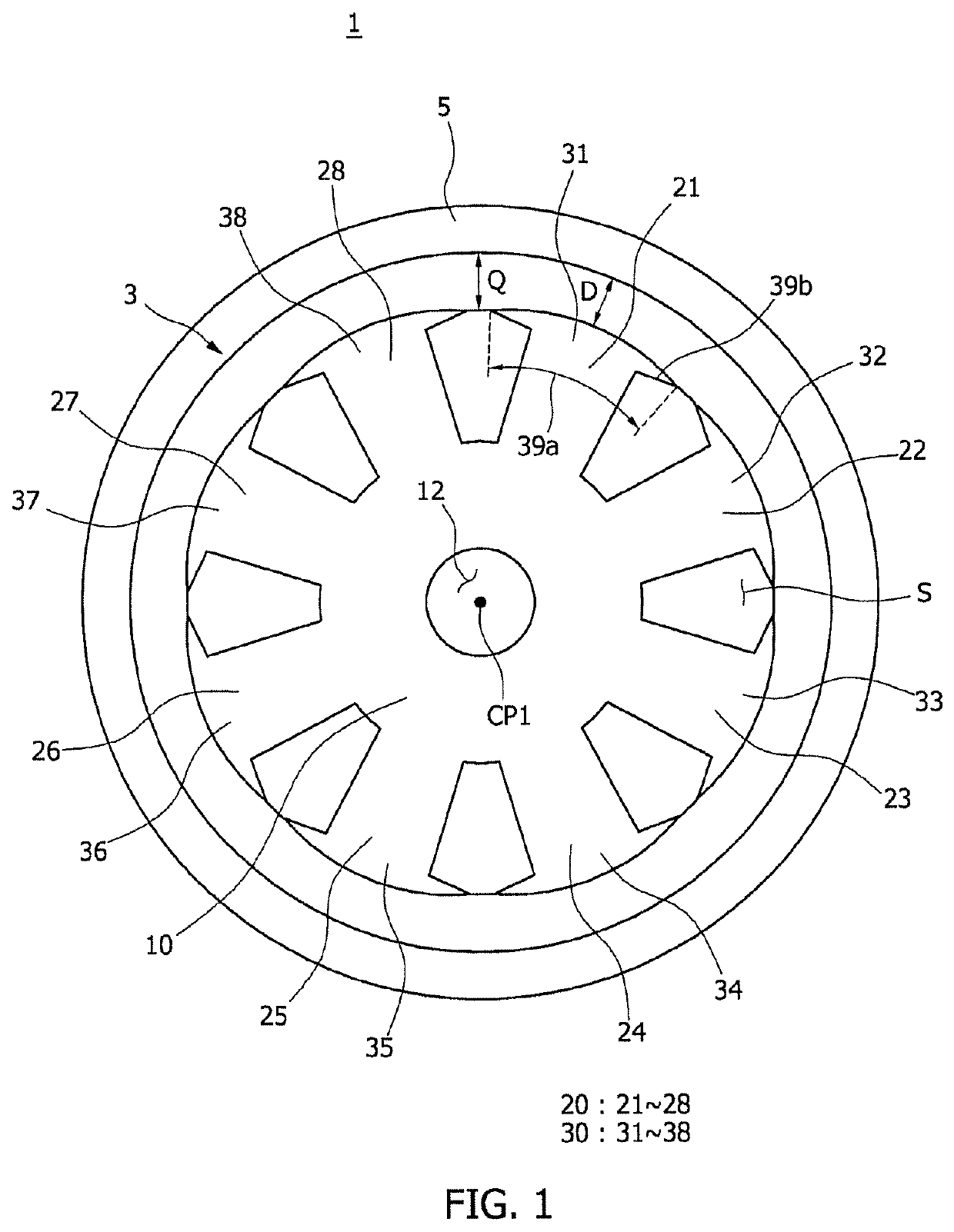
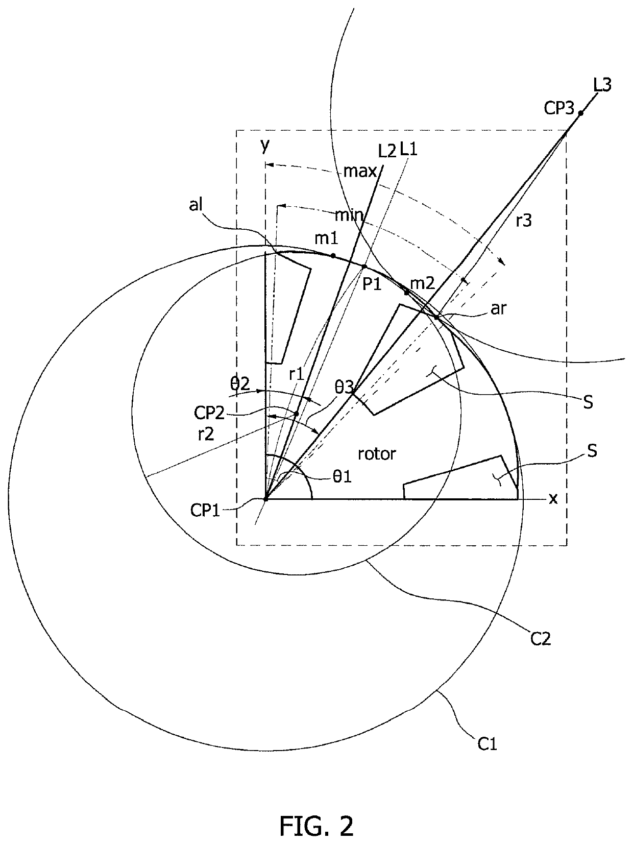
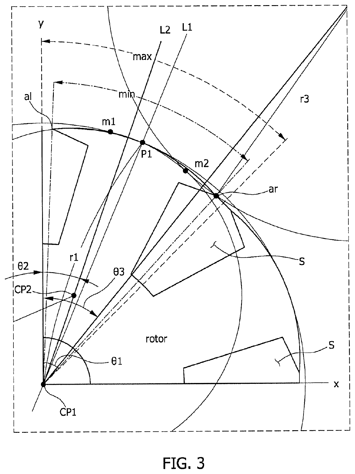
[0077]In addition, in a rotor 3 for a wound-rotor motor according to one embodiment of the present invention, a cross-sectional area from a first pole shoe left end position al1 to a first pole shoe outermost position P1 of a first pole shoe outer side surface 39a may be formed along a first imaginary circle C1, a cross-sectional area from the first pole shoe outermost position P1 to a second intersection point m2 may be formed along a second imaginary circle C2, and a cross-sectional area from the second intersection point m2 to a first pole shoe right end position ar2 may be formed along a third imaginary circle C3.

[0078]Referring to FIGS. 4 and 5, in a modified embodiment of the present invention, a rotor 103 for a wound-rotor motor may decrease a torque ripple while a total size of a motor does not increase and a torque does not decrease by designing a first pole shoe outer side surface 139a.

[0079]In one embodiment of the present invention, a fourth imaginary circle C4 may be a...


PUM


Abstract

Disclosed herein is a rotor for a wound-rotor motor. The rotor for a wound-rotor motor includes: a rotor core including a hollow formed in a central portion thereof and coupled to a shaft; a teeth portion radially formed on an outer side surface of the rotor; and a pole shoe formed to extend from an end portion of the teeth portion in one direction and including a part of a cross section of an outer side surface formed in an arc shape of a first imaginary circle (C1) having a first radius (r1) which is a distance from a central point (CP1) of the hollow to an outermost position (P1) thereof.

Description

CROSS-REFERENCE TO RELATED APPLICATION[0001]This application claims priority to and the benefit of Korean Patent Application No. 10-2016-0170395, filed on Dec. 14, 2016, the disclosure of which is incorporated herein by reference in its entirety.BACKGROUND1. Field of the Invention[0002]The present invention relates to a rotor for a wound-rotor motor and a wound-rotor motor having the same.2. Discussion of Related Art[0003]Generally, vehicles include starter motors configured to start an engine and alternators configured to generate electricity using a rotary force of the engine. When a driver starts a vehicle, an ignition switch is connected to a power source of a battery by an operation of the driver, a driving force generated by a starter motor supplied with power rotates an engine, and thus the vehicle is started.[0004]In comparison, an alternator, which is connected to a driving portion of an engine, charges a battery with alternating current (AC) power using a rectifier or the ...

Claims


Application Information

Patent Timeline
Patent Type & Authority Patents(United States)
IPC IPC(8): H02K21/12H02K1/27H02K1/24H02K3/47H02K3/52H02K21/20H02P6/08H02K1/26
CPCH02K1/243H02K1/265H02K1/2773H02K3/47H02P6/08H02K3/528H02K1/24H02K21/20H02K2213/03H02K1/165H02K1/22
Inventor PARK, SEUNG YOUNG
Owner HL MANDO CORP
Why Eureka
Try Eureka