
Ultrawide-band communication system and method

a communication system and impulse communication technology, applied in the field of communication, can solve the problems of low power consumption, channelization and cost, reuse of available resources, etc., and achieve the effects of reducing distortion, increasing bandwidth, and adding fidelity

Inactive Publication Date: 2011-07-19
HUMATICS CORP
View PDF12 Cites 4 Cited by
  • Summary
  • Abstract
  • Description
  • Claims
  • Application Information

AI Technical Summary

Benefits of technology

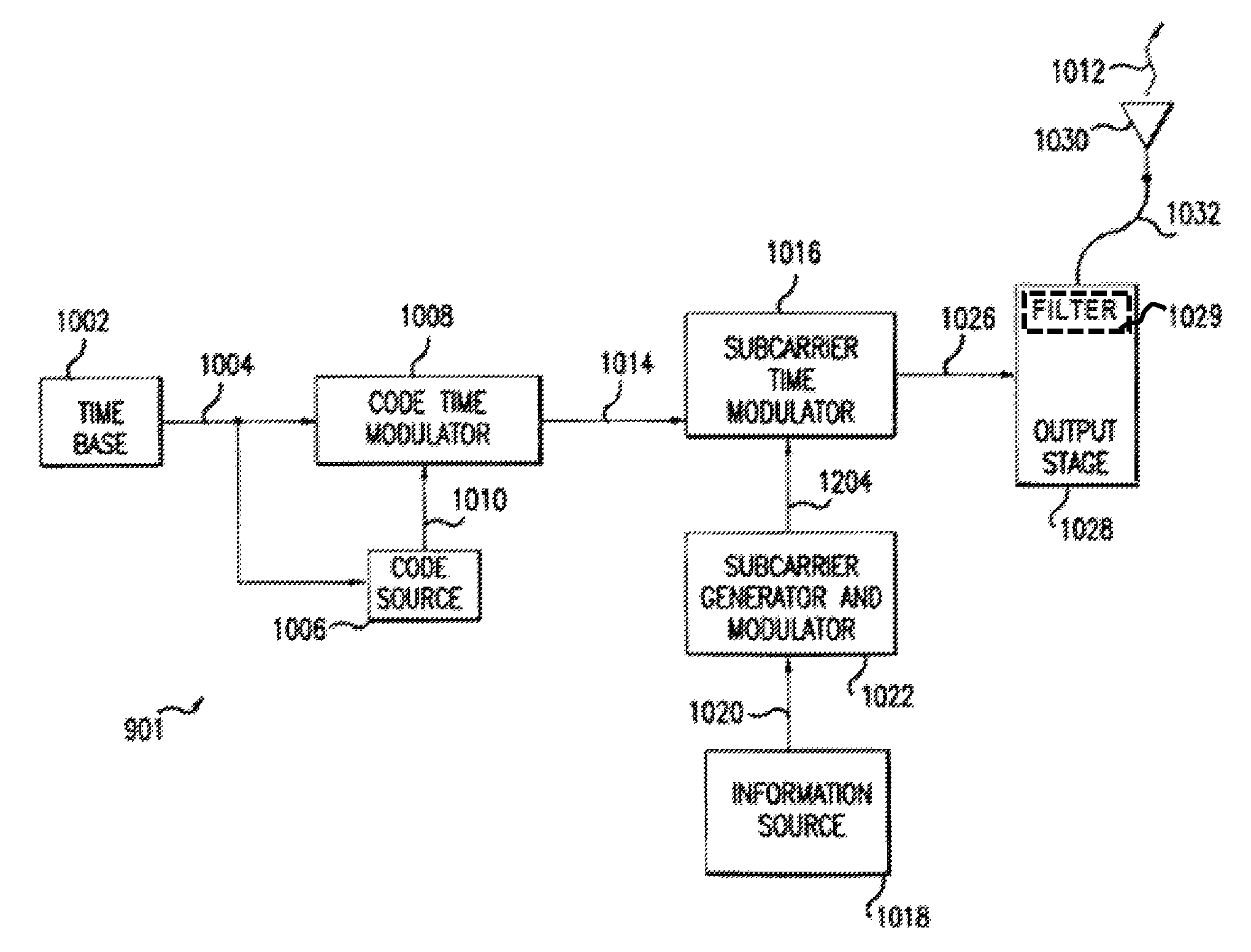
"The present invention is a communication system that uses impulse radio to transmit information between a transmitter and a receiver. The system uses subcarriers to add channelization, smoothing, and fidelity to the impulse radio signals. The transmitter has a subcarrier generator and modulator that modulate a periodic timing signal with an information signal. The modulated timing signal is used to generate monocycle pulses, which are sent to the receiver through a transmission line. The receiver has a cross correlator, decode source, decode timing modulator, and adjustable time base to detect the impulse radio signals. The system uses ultrawide-band signals for communication. The technical effects of the invention include improved communication speed, reliability, and security."

Problems solved by technology

Designers of radio technology for personal communications devices, medical and military devices, and the like, are currently faced with several development challenges.
Low power consumption, reuse of available spectrum, channelization and cost are four of the main issues.
However, generally accepted principles in continuous wave (CW) radio technology do not readily lend themselves to time domain systems, such as impulse radio.

Method used


Image

  • Ultrawide-band communication system and method
  • Ultrawide-band communication system and method
  • Ultrawide-band communication system and method

Examples


Embodiment Construction

I. Overview

[0064]The impulse radio communication system is an ultrawide-band time domain system that operates in the time domain and uses one or more subcarriers to provide channelization, smoothing and fidelity. A single impulse radio transmission (e.g., a link) can therefore communicate many independent channels simultaneously by employing different subcarriers for each channel.

[0065]The impulse radio transmitter according to the present invention uses modulated subcarrier(s) for time positioning a periodic timing signal or a coded timing signal. Alternatively, the coded timing signal can be mixed (or summed) with the modulated subcarrier(s) and the resultant signal used to time modulate the periodic timing signal. Direct digital modulation of data is another form of subcarrier modulation for impulse radio signals. Direct digital modulation can be used alone to time modulate the periodic timing signal or the direct digitally modulated periodic timing signal can be further modulate...


PUM


Abstract

An impulse radio communications system using one or more subcarriers to communicate information from an impulse radio transmitter to an impulse radio receiver. The impulse radio communication system is an ultrawide-band time domain system. The use of subcarriers provides impulse radio transmissions added channelization, smoothing and fidelity. Subcarriers of different frequencies or waveforms can be used to add channelization of impulse radio signals. Thus, an impulse radio link can communicate many independent channels simultaneously by employing different subcarriers for each channel. The impulse radio uses modulated subcarrier(s) for time positioning a periodic timing signal or a coded timing signal. Alternatively, the coded timing signal can be summed or mixed with the modulated subcarrier(s) and the resultant signal is used to time modulate the periodic timing signal. Direct digital modulation of data is another form of subcarrier modulation for impulse radio signals. Direct digital modulation can be used alone to time modulate the periodic timing signal or the direct digitally modulated the periodic timing signal can be further modulated with one or more modulated subcarrier signals. Linearization of a time modulator permits the impulse radio transmitter and receiver to generate time delays having the necessary accuracy for impulse radio communications.

Description

CROSS-REFERENCE TO RELATED APPLICATIONS[0001]This application is a continuation of U.S. patent application Ser. No. 10 / 196,121, filed Jul. 12, 2002, now U.S. Pat. No. 6,847,675, which is a continuation of U.S. patent application Ser. No. 09 / 037,704, filed Mar. 10, 1998, now U.S. Pat. No. 6,430,208, which is a continuation of U.S. patent application Ser. No. 08 / 949,144, filed Oct. 10, 1997, now U.S. Pat. No. 5,995,534, which is a division of U.S. patent application Ser. No. 08 / 309,973, filed Sep. 20, 1994, now U.S. Pat. No. 5,677,927, the specifications of which are incorporated herein by reference in their entireties.BACKGROUND OF THE INVENTION[0002]1. Field of the Invention[0003]The present invention relates to the field of communications, and more particularly, the present invention relates to ultrawide-band impulse communication systems and methods employing subcarriers.[0004]2. Background Art[0005]Designers of radio technology for personal communications devices, medical and mil...

Claims


Application Information

Patent Timeline
Patent Type & Authority Patents(United States)
IPC IPC(8): H04B1/69H04B1/707H04B1/7075H04B1/708H04B1/7163H04B1/7176H04B1/7183H04B14/02H04L27/26
CPCH04B1/69H04B1/70753H04B1/71632H04B1/71635H04B1/71637H04B1/7176H04B1/7183H04B14/026H04L27/2601H04B1/707H04B1/708H04B2001/6908H04B2201/70707H04L27/2602Y02D30/70
Inventor FULLERTON, LARRY W.COWIE, IVAN A.
Owner HUMATICS CORP
Learn More