Sound convertor

A converter and sound technology, applied in the direction of sensors, electrical components, planar diaphragms, etc., can solve problems such as thermal deformation, achieve the effect of suppressing deformation and reducing internal heat

Active Publication Date: 2019-04-05
EM TECHNOLOGY CO LTD
View PDF5 Cites 1 Cited by
  • Summary
  • Abstract
  • Description
  • Claims
  • Application Information

AI Technical Summary

Problems solved by technology

[0005] In addition, the applicant's conventional patent has the risk of therma

Method used


Image

  • Sound convertor
  • Sound convertor
  • Sound convertor

Examples


Example Embodiment

[0018] Hereinafter, a preferred embodiment of the sound converter according to the present invention will be described in detail with reference to the accompanying drawings.
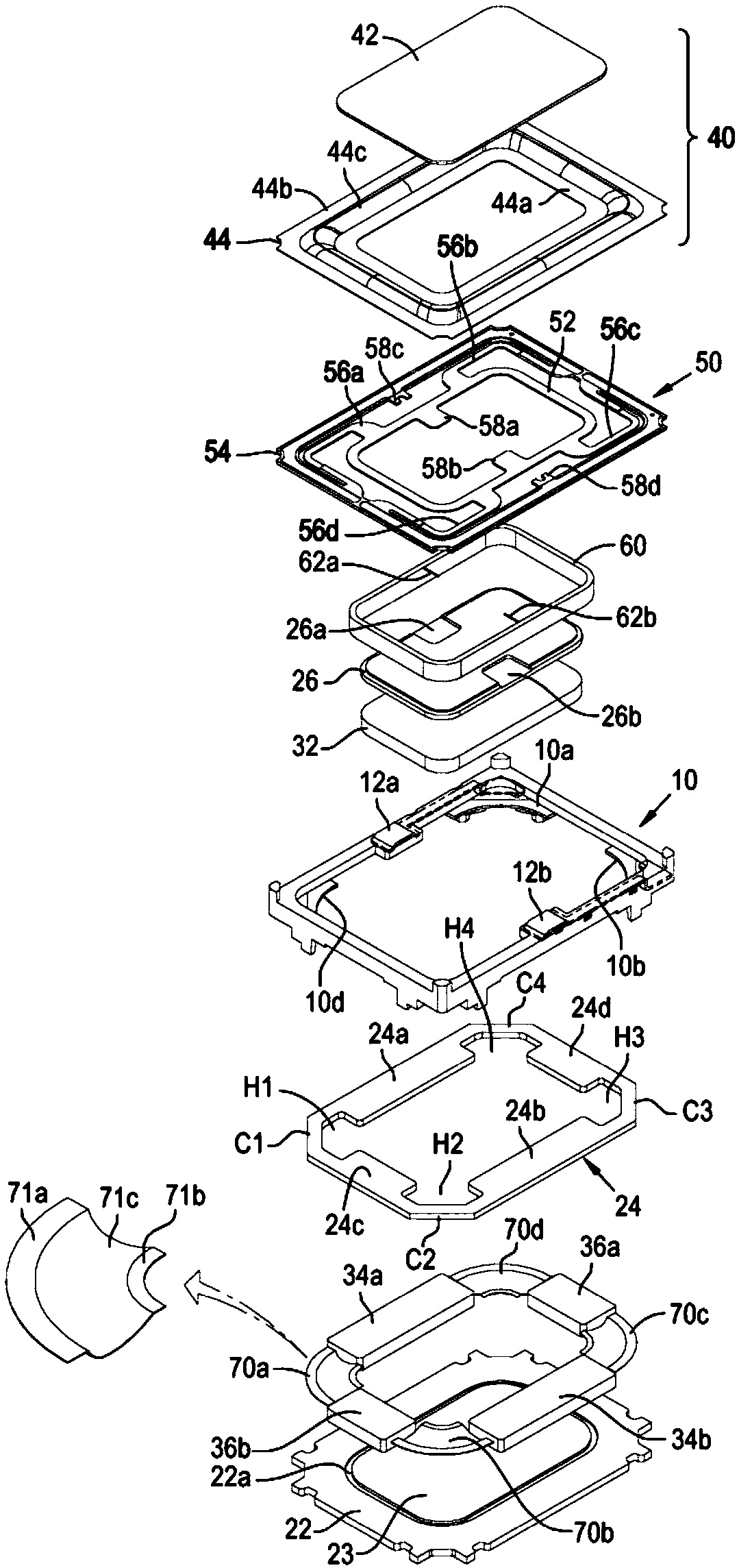
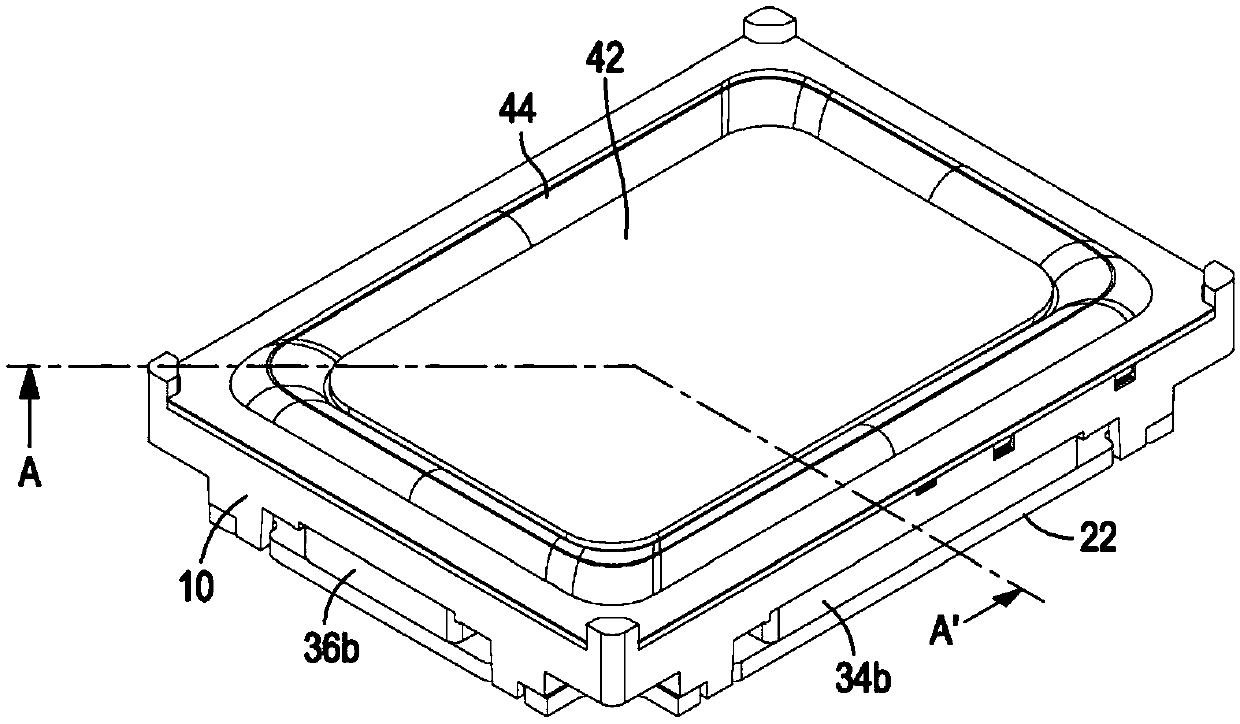
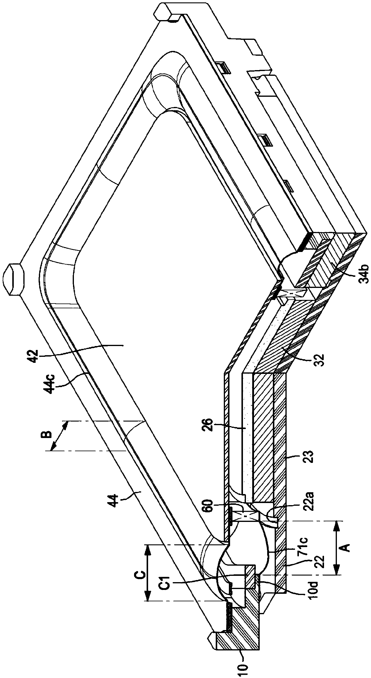
[0019] figure 1 Is an exploded perspective view of the sound converter according to the present invention, figure 2 Is a perspective view of the sound converter according to the present invention, and image 3 Is along figure 2 A cross-sectional perspective view taken along the line A-A'.

[0020] The sound converter includes: a frame 10; a bottom plate, the bottom plate is mounted on the bottom surface of the frame 10 and the bottom plate includes an outer bottom plate 22 and an inner bottom plate 23; a top plate, the top plate includes an outer top plate 24 and an inner top plate 26; a central magnet 32, The central magnet 32 ​​is installed between the inner top plate 26 and the inner bottom plate 23; the first sub-magnet 34a, the second sub-magnet 34b, the third sub-magnet 36a and the fourth sub-magnet 36...


PUM


Abstract

The invention relates to a sound converter, particularly a sound converter including suspension devices used for connecting the lower end or lower end side surface of a voice coil to a frame so as tosuppress splitting and vibration. The sound converter includes a frame; a bottom plate including an outer bottom plate and an inner bottom plate; a top plate including an outer top plate and an innertop plate; a center magnet mounted between the inner top plate and the inner bottom plate; first to fourth sub-magnets mounted between the outer top plate and the outer bottom plate and spaced apart from the center magnet by a magnetic gap; a first suspension device including a center dome member and an edge dome member mounted at the top part of the frame; a second suspension device including FPCB and attached to the bottom surface of a vibrating diaphragm; a voice coil having a lower end positioned in the magnetic gap and an upper end attached to the bottom surface of the second suspension device; and a third suspension device including first to fourth dampers. The dampers penetrate space among the sub-magnets to connect the lower end of the voice coil to the frame.

Description

technical field [0001] The present invention relates to a sound transducer, and more particularly to a sound transducer comprising a suspension for connecting the lower end or lower end side surface of a voice coil to a frame to suppress split vibrations . Background technique [0002] Conventional sound transducers (eg, microspeakers, etc.) do not use broadband sound sources due to limitations in communication technology. However, with the development of information communication technology, the reproduction bandwidth of the sound source to be reproduced in the sound transducer has been widened, and as the required power increases, the structure of the conventional sound transducer is Reliability is limited. [0003] In order to solve these problems, the present applicant filed and registered Korean Patent No. 10-1200435 (hereinafter, referred to as "conventional patent") entitled "High power microspeaker (high power microspeaker)", which high power micro A speaker inclu...

Claims


Application Information

Patent Timeline
IPC IPC(8): H04R9/06H04R9/04H04R9/02
CPCH04R9/02H04R9/04H04R9/06H04R9/022H04R9/025H04R31/006H04R9/043H04R7/04H04R31/003H04R7/20H04R9/045
Inventor 金千明郑性哲南瑟基河敬辅
Owner EM TECHNOLOGY CO LTD
Why Eureka
Try Eureka