Switch-mode power supply and control circuit and control method thereof

A power supply and control circuit technology, applied in electrical components, output power conversion devices, etc., can solve problems such as total harmonic distortion

Active Publication Date: 2015-06-24
RICHTEK TECH
View PDF5 Cites 2 Cited by
  • Summary
  • Abstract
  • Description
  • Claims
  • Application Information

AI Technical Summary

Problems solved by technology

[0004] The aforementioned typical isolated switching power supplies 100 and 200 have the problem of

Method used


Image

  • Switch-mode power supply and control circuit and control method thereof
  • Switch-mode power supply and control circuit and control method thereof
  • Switch-mode power supply and control circuit and control method thereof

Examples


Embodiment Construction

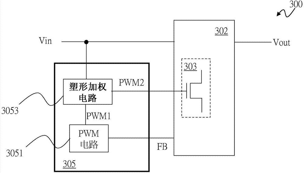
[0059] see Figures 2A-2C , showing a first embodiment of the present invention. Such as Figure 2A As shown, the switching power supply 300 includes a power stage circuit 302 and a control circuit 305 . The power stage circuit 302 switches the power switch 303 to convert the input voltage Vin to the output voltage Vout according to a driving signal GATE. The control circuit 305 is coupled to the power stage circuit 302 and includes a pulse width modulation (PWM) circuit 3051 and a shaping weighting circuit 3053 . The PWM circuit 3051 generates a PWM signal PWM1 according to the feedback signal FB. The feedback signal FB is related to the output voltage Vout. For example, it can be obtained from the output terminal of the power stage circuit 302, or from the output voltage Vout, or from the auxiliary winding when the power stage circuit 302 is an isolated power conversion circuit using a transformer. available everywhere. The shaping weighting circuit 3053 is coupled to t...


PUM


Abstract

The invention provides a switch-mode power supply and a control circuit and control method thereof. The switch-mode power supply converts input voltage into output voltage and comprises a power level circuit and a control circuit, wherein the power level circuit is used for switching at least one power switch to convert input voltage into output voltage according to a driving signal, the control circuit is coupled with the power level circuit and comprises a pulse width modulation (PWM) circuit and a shaping and weighing circuit, the PWM circuit is used for generating a PWM signal according to a feedback signal, and the shaping and weighing circuit is coupled with the PWM circuit to receive the PWM signal and delay the time when rising edge or falling edge occurs in the PWM signal in each period for a preset period of time according to input voltage, so that the driving signal is generated.

Description

technical field [0001] The present invention relates to a switchable power supply and its control circuit and control method, in particular to a switchable power supply for improving Total Harmonic Distortion (THD), its control circuit and control method. Background technique [0002] Figure 1A A schematic diagram of a typical isolated switching power supply 100 is shown. Such as Figure 1A As shown, the voltage to be rectified Vac is, for example, a DC or AC voltage, and is rectified by the rectification circuit 101 to generate the input voltage Vin. The rectification circuit 101 is, for example, a bridge rectification circuit. The isolated power converter circuit 100 utilizes the transformer circuit 102 therein to receive an input voltage Vin and convert it into an output voltage Vout. Wherein, the isolated switching power supply 100 includes the aforementioned transformer circuit 102 , power switch 103 , control circuit 105 , current sensing circuit 106 , and voltage s...

Claims


Application Information

Patent Timeline
IPC IPC(8): H02M1/12
CPCH02M1/12
Inventor 廖家玮邱仁炼陈培元
Owner RICHTEK TECH
Why Eureka
Try Eureka