Decoding device, decoding method, encoding device, and encoding method
a decoding device and a technology of encoding, applied in the field of decoding devices and decoding methods, can solve the problems of not supporting coding methods using less amount of codes (lower bit rate) than mpeg1, and mpeg2 does not support coding methods with a higher compression rate, so as to improve the encoding efficiency of blocks of a size other than 4 by 4 pixels
- Summary
- Abstract
- Description
- Claims
- Application Information
AI Technical Summary
Benefits of technology
Problems solved by technology
Method used
Image
Examples
first embodiment
Example of Configuration of Embodiment of Encoding Device
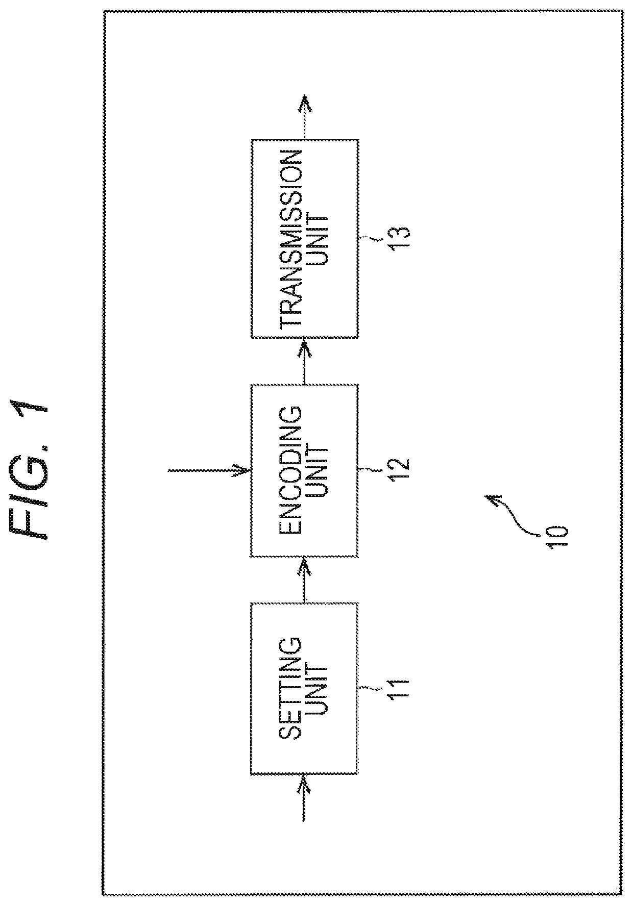
[0072]FIG. 1 is a block diagram illustrating an example of configuration of an embodiment of an encoding device to which the present disclosure is applied.
[0073]An encoding device 10 of FIG. 1 includes a setting unit 11, an encoding unit 12, and a transmission unit 13, and encodes an image according to a method based on an HEVC method.
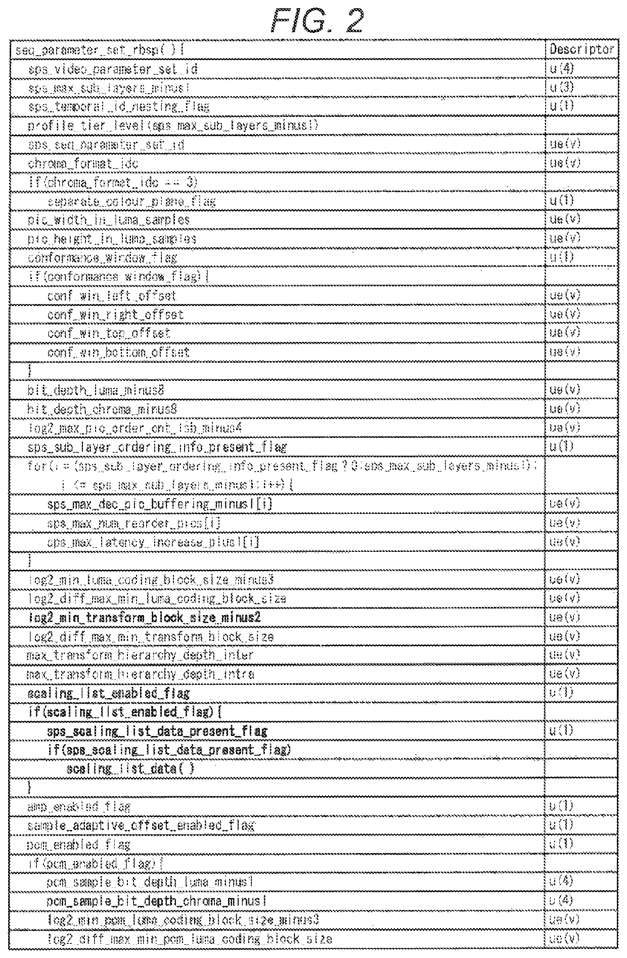
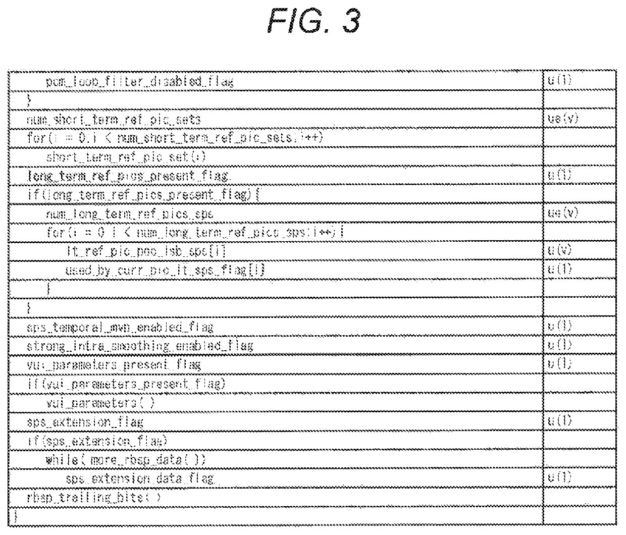
[0074]More specifically, the setting unit 11 of the encoding device 10 sets a SPS (Sequence Parameter Set) including minimum TU size information indicating the minimum size of the TU which is a size of a TU (orthogonal transform block) where transform skip can be performed in accordance with user's command and the like. The setting unit 11 also sets a PPS (Picture Parameter Set) including skip permission information indicating whether application of transform skip to the TU of the minimum size is permitted or not. Further, the setting unit 11 sets VUI (Video Usability Information), SEI (Supplemen...
second embodiment
[0284](Explanation About Computer to which the Present Disclosure is Applied)
[0285]The above series of processing may be executed by hardware, or may be executed by software. When the series of processing is executed by software, programs constituting the software are installed to the computer. Here, the computer includes a computer incorporated into dedicated hardware and, for example, a general-purpose personal computer capable of executing various kinds of functions by installing various kinds of programs.
[0286]FIG. 18 is a block diagram illustrating an example of configuration of hardware of a computer which executes the above series of processing by using programs.
[0287]In a computer, a CPU (Central Processing Unit) 201, a ROM (Read Only Memory) 202, a RAM (Random Access Memory) 203 are connected with each other via a bus 204.
[0288]The bus 204 is further connected with an input / output interface 205. The input / output interface 205 is connected with an input unit 206, an output u...
third embodiment
[0294](Application to Multi-Viewpoint Image Coding / Multi-Viewpoint Image Decoding)
[0295]The above series of processing can be applied to multi-viewpoint image coding / multi-viewpoint image decoding. FIG. 19 illustrates an example of multi-viewpoint image coding method.
[0296]As illustrated in FIG. 19, a multi-viewpoint image includes images for multiple view points (views). Multiple views of this multi-viewpoint image include a base view encoded / decoded using only the image of the view in question without using any image of another view, a non-base view encoded / decoded using any image of another view. The non-base view may use the image of the base view, or may use the image of another non-base view.
[0297]When the multi-viewpoint image as shown in FIG. 19 is encoded / decoded, the image of each view is encoded / decoded, but the method of the first embodiment may be applied to the encoding / decoding of each view. By doing so, the encoding efficiency where the transform skip is applied to a...
PUM
 Abstract
Description
Claims
Application Information
 - R&D
- Intellectual Property
- Life Sciences
- Materials
- Tech Scout
- Unparalleled Data Quality
- Higher Quality Content
- 60% Fewer Hallucinations
Browse by: Latest US Patents, China's latest patents, Technical Efficacy Thesaurus, Application Domain, Technology Topic, Popular Technical Reports.
© 2025 PatSnap. All rights reserved.Legal|Privacy policy|Modern Slavery Act Transparency Statement|Sitemap|About US| Contact US: help@patsnap.com


