Anti-torsion structure for an A-frame hauling trailer

a technology for hauling trailers and a frame, applied in the field of trailers, can solve the problems of trailer instability, inability to separate and evenly distribute on both sides of the trailer, and other dangers of possible contact with roadways or items, and achieve the effects of minimizing twisting, minimizing twisting of the drop deck, and reducing the weight of the at least two main beams

Active Publication Date: 2020-06-23
REITNOUER MILES A
View PDF20 Cites 1 Cited by
  • Summary
  • Abstract
  • Description
  • Claims
  • Application Information

AI Technical Summary

Benefits of technology

[0008]A trailer for hauling payload (e.g., jumbo pane glass, etc.) positioned on opposite sides of the trailer which experiences minimized twisting is disclosed. The trailer comprises: a trailer body having at least two main beams that support an elevated front deck and a drop deck, wherein the drop deck has a rear portion positioned over a wheel system; a plurality of A-frames transversely positioned on the drop deck; and an anti-torsion structure that couples the plurality of A-frames together and to the at least two main beams at the elevated front deck and at the rear portion, wherein the anti-torsion structure minimizes twisting of the drop deck, and without increasing the weight of the at least two main beams, when the payload is positioned on the drop deck and against sides of the plurality A-frames.
[0009]A method for forming a trailer that is configured to haul payload (e.g., jumbo pane glass, etc.) positioned on opposite sides of the trailer while experiencing minimized twisting is disclosed. The method comprises: forming a trailer body having at least two main beams that support an elevated front deck and a drop deck, and wherein the drop deck has a rear portion positioned over a wheel system; positioning a plurality of A-frames transversely on the drop deck; and coupling the plurality of A-frames together and to the at least two main beams at the elevated front deck and at the rear portion using an anti-torsion structure, and wherein the anti-torsion structure minimizes twisting of the drop deck, and without increasing the weight of the at least two main beams, when the payload is positioned on the drop deck and against sides of the plurality of A-frames.
[0010]An anti-torsion structure configured for minimizing the twisting of a trailer that hauls payload (e.g., jumbo pane glass, etc.) positioned on opposite sides of the trailer is disclosed. The trailer has a body formed of at least two main beams that support an elevated front deck and a drop deck and wherein the drop deck has a rear portion positioned over a wheel system and wherein the drop deck includes a plurality of A-frames positioned transversely on the drop deck and against which the payload is positioned. The anti-torsion structure comprises: a plurality of bars that are connected between tops of the plurality of A-frames; a first member that is connected to the at least two main beams at the elevated front deck on a first end of the first member and is connected to a top of a forward-most A-frame on a second end of the first member; and a second member that is connected to the at least two main beams at the rear portion on a first end of the second member and is connected to a top of a rear-most A-frame on a second end of the second member.
[0011]A method for minimizing the twisting of a trailer that hauls payload (e.g., jumbo pane glass, etc.) positioned on opposite sides of the trailer is disclosed. The trailer includes a body formed of at least two main beams that support an elevated front deck and a drop deck and wherein the drop deck has a rear portion positioned over a wheel system and wherein the drop deck includes a plurality of A-frames positioned transversely on the drop deck and against which the payload is positioned. The method comprises: coupling the A-frames together by connecting a plurality of bars between tops of the plurality of A-frames; connecting a first member to the at least two main beams at the elevated front deck on a first end of the first member and connecting a second end of the first member to a top of a forward-most A-frame; and connecting a second member to the at least two main beams at the rear portion on a first end of the second member and connecting a second end of the second member to a top of a rear-most A-frame.

Problems solved by technology

However, in many cases, the jumbo glass panes to be transported are provided such that they cannot be separated and evenly distributed on both sides of the trailer.
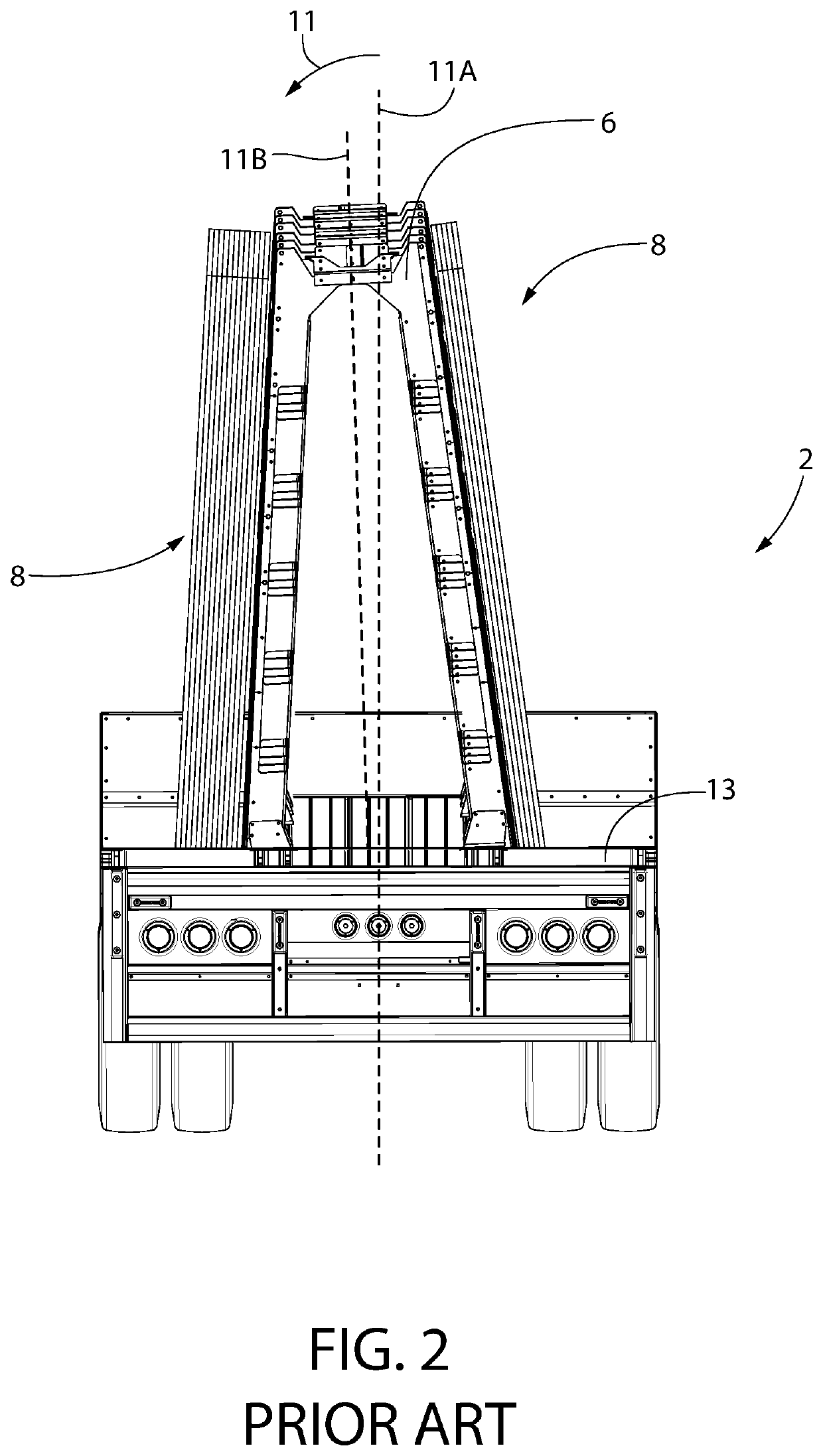
This twisting / leaning 11 not only makes the trailer unstable but it also creates another dangerous situation of possible contact with the roadway or items in the roadway during travel.
A large continuous tarp is a preferred method of covering the payload during transport but that type of tarp can have significant weight itself and in order to transport a particular payload of jumbo glass panes, the trailer owner is forced to forego the use of the continuous tarp in order to make the delivery while complying with the roadway regulations.
As such, a more cumbersome and time-consuming use of individual covers over the glass panes themselves is required.

Method used


Image

  • Anti-torsion structure for an A-frame hauling trailer
  • Anti-torsion structure for an A-frame hauling trailer
  • Anti-torsion structure for an A-frame hauling trailer

Examples


Embodiment Construction

[0025]Referring now to the figures, wherein like reference numerals represent like parts throughout the several views, exemplary embodiments of the present disclosure will be described in detail. Throughout this description, various components may be identified having specific values, these values are provided as exemplary embodiments and should not be limiting of various concepts of the present invention as many comparable sizes and / or values may be implemented.

[0026]FIG. 4 depicts the anti-torsion A-frame hauling trailer 20 of the present invention using a drop deck configuration 21 including side rails 22. The trailer 20 comprises a trailer body having a pair of main beams 24A / 24B that support an elevated front deck 26 and which run the full length of the trailer 20 culminating in a rear portion 28 that rests on a wheel system 30. A plurality of A-frames 32 straddle and are mounted transversely to the main beams 24A / 24B and are connected to the main beams 24A / 24B and to feet 34 o...


PUM


Abstract

A drop-deck trailer for hauling heavy loads (e.g., jumbo glass panes) positioned on each side of the drop-deck and which minimizes trailer twisting / leaning is provided. The drop deck includes a plurality of transversely-mounted A-frames that are coupled through an anti-torsion structure (ATS) to each other and to at least two trailer main beams at an elevated front deck and at a rear portion of the drop-deck for transferring the load from each side of the trailer and into the at least two main beams. The ATS includes tie bars for connecting the tops of the A-frames together, a front support for connecting the forward-most A-frame to the main beams and an end support for connecting the rear-most A-frame to the main beams. The ATS minimizes twisting / leaning of the trailer without adding any significant weight to the trailer itself. This permits the transport of increased payload on the trailer, including a continuous tarp for covering the payload during transport.

Description

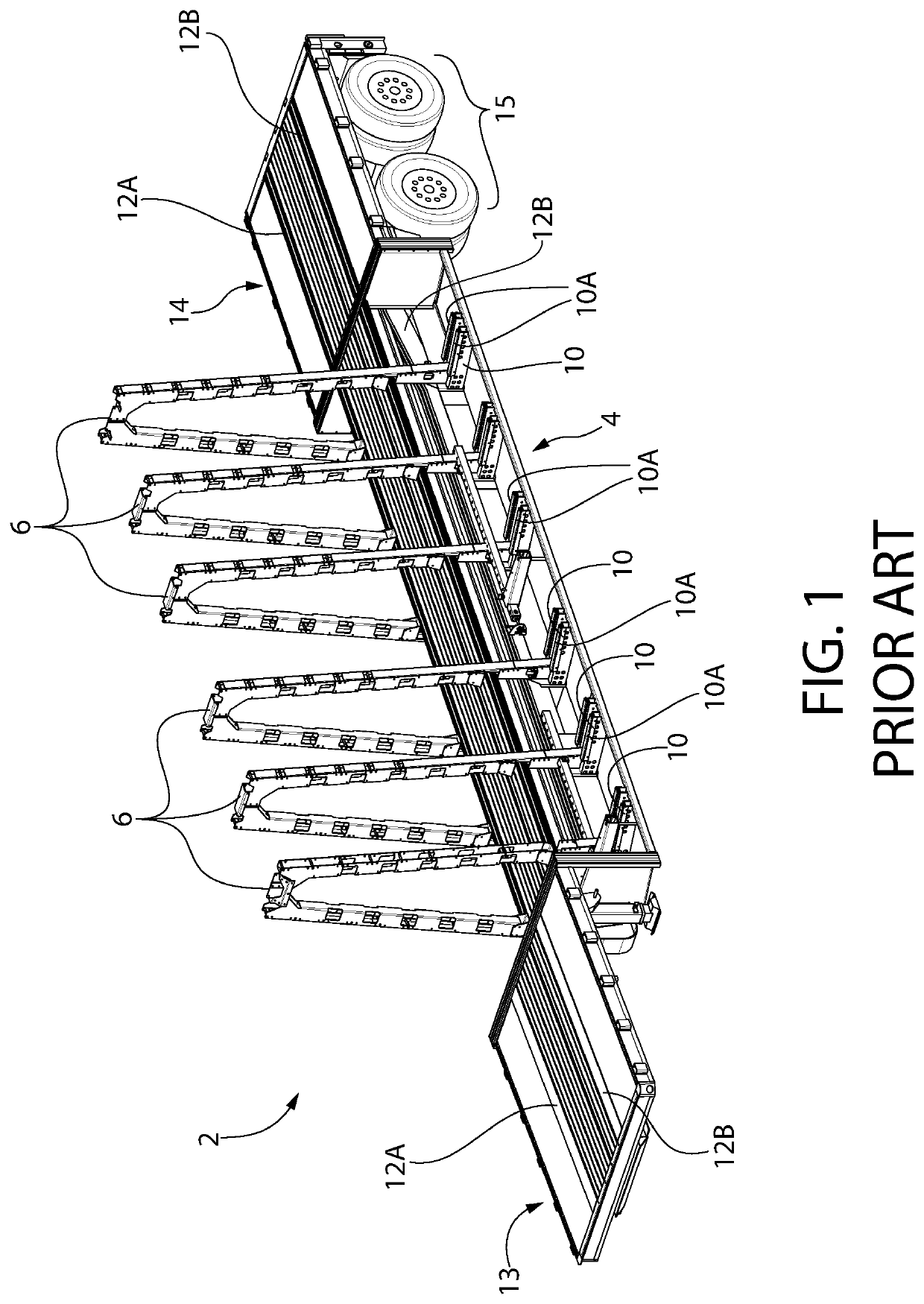
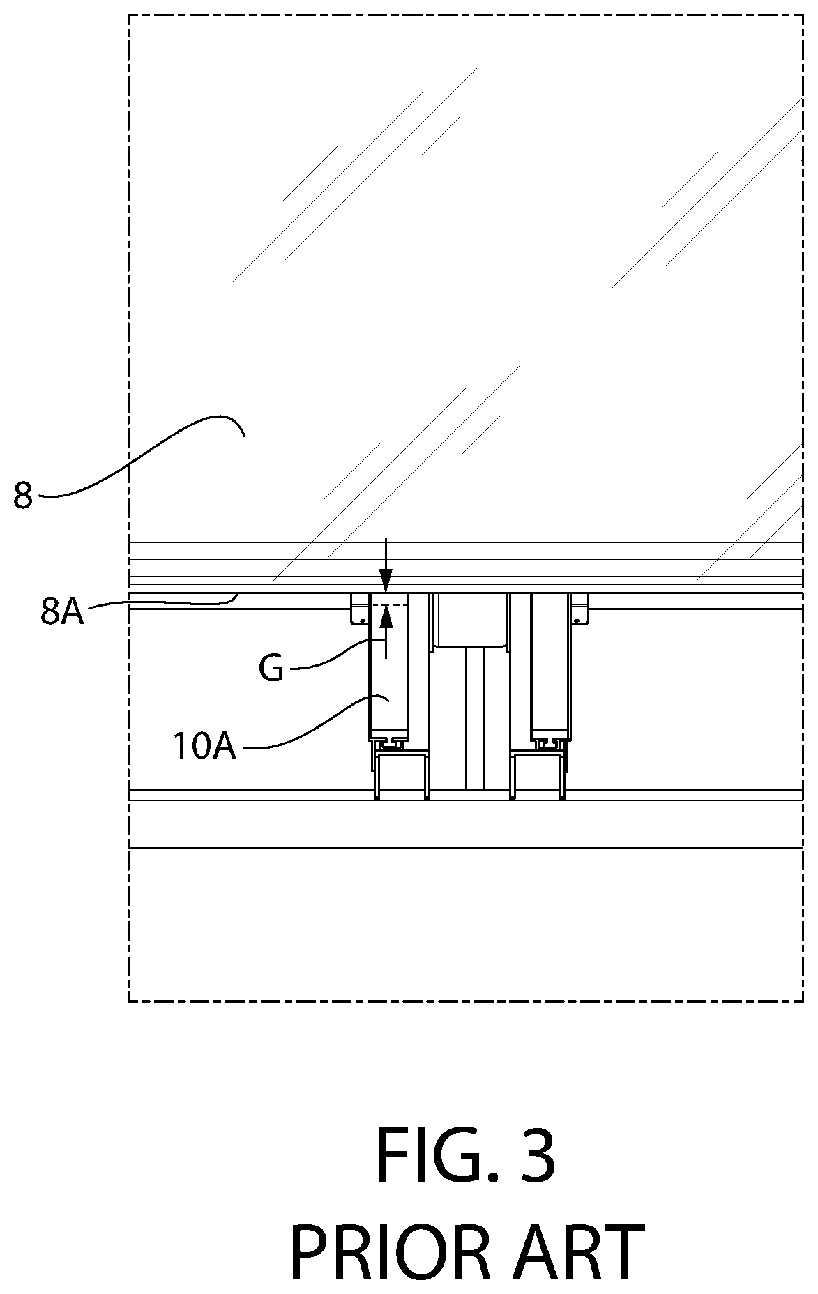
BACKGROUND OF THE INVENTION[0001]The present invention relates trailers and more particularly to a trailer that uses an anti-torsion structure connected to A-frames for hauling heavier loads (e.g., jumbo glass panes) on both sides of the trailer and to reduce twisting of the trailer where the loads are non-symmetrical and without significantly adding to the trailer's weight.[0002]FIG. 1 depicts a prior art conventional trailer 2 using a drop-deck design including side rails 4 with a plurality of transversely positioned A-frames 6 for hauling jumbo glass panes 8 (FIG. 2). The trailer 2 comprises main beams 12A / 12B that support an elevated front deck 13 and which run the full length of the trailer 2 culminating in a rear portion 14 that rests on a wheel system 15. The A-frames 6 straddle and are mounted to the main beams 12A / 12B and are connected to the main beams 12A / 12B and to feet 10 on each side of the trailer 2. The side rails 4 are connected to the feet 10 on each side of the tr...

Claims


Application Information

Patent Timeline
Patent Type & Authority Patents(United States)
IPC IPC(8): B62D21/20B62D53/06B60P3/00
CPCB60P3/002B62D53/06B62D21/20
Inventor REITNOUER, MILES A.
Owner REITNOUER MILES A
Why Eureka
Try Eureka