Torsional vibration damping assembly for a drive train of a vehicle

a technology of torsional vibration and assembly, which is applied in the direction of rotating vibration suppression, spring/damper, shock absorber, etc., can solve the problem that torsional vibration cannot be reduced in a simple coupled oscillator

Active Publication Date: 2020-06-23
ZF FRIEDRICHSHAFEN AG
View PDF12 Cites 0 Cited by
  • Summary
  • Abstract
  • Description
  • Claims
  • Application Information

AI Technical Summary

Benefits of technology

[0007]A further advantageous embodiment provides that a working medium comprising a viscous medium, or a gas, or a combination of a viscous medium and a gas is located in the working chamber of the displacer unit and in the working chamber of the slave cylinder. In this regard, a viscous medium such as a hydraulic fluid, for example, is especially advantageous because liquids are not compressible and are advantageously suitable as working medium for conveying in the form of pressure pulses. Accordingly, the alternating torques from the drive unit which are converted by the displacer unit to alternating pressures can be conveyed directly to the slave cylinder via the working medium, i.e., a hydraulic fluid in this case. Since the slave cylinder is in turn operatively connected to the damper mass arrangement, an advantageous reduction of vibrations can be achieved in this way.
[0011]A further embodiment provides that the working chamber of the displacer unit is operatively connected to a working chamber of the slave cylinder by a connection line. The connection line is constructed such that it receives the working medium, i.e., the liquid or the gas or a combination of liquid and gas, with low pumping loss. This means that the alternating pressures of the working medium should not cause an elastic deformation of the connection line, which could have disadvantageous consequences for the control behavior of the damper mass arrangement and can therefore also be disadvantageous for vibration damping.
[0013]Further, it may be advantageous that the damping arrangement comprises a supply pump and / or a pressure storage and / or a control unit, and the supply pump and / or the pressure storage and / or the control unit is operatively connected to the working chamber of the slave cylinder. This can be advantageous, for one, in order to compensate for leakage and / or to achieve a load point shift of the damper mass arrangement. To this end, the pressure of the working medium can be changed through the supply pump and the pressure storage. The control unit which can control the needed pressure of the working medium can also be advantageous for this purpose. The supply pump can advantageously be an oil pressure pump or a compressor. The control unit advantageously includes sensors for detecting pressure, pressure control valves and pressure switching valves.
[0014]Further, the slave cylinder can have a load spring element, and the load spring element acts against a working direction of a volume change V2 of the working chamber of the slave cylinder. This can make possible an additional shift of the operating point of the effective damper stiffness by increasing the fluid pressure of the working medium in the displacer unit and in the slave cylinder against the load spring. This load spring can be constructed as a steel spring or also as a gas spring. Through the alternating torque at the displacer, the damper mass arrangement which is fixed with respect to rotation relative to rotational axis A and which comprises the damper mass and the damper stiffness arrangement is excited via the alternating pressure on the slave cylinder. With suitable tuning, the damper mass arrangement operates in phase opposition and accordingly at least partially cancels the vibrations.

Problems solved by technology

However, the disadvantage is that the torsional vibrations cannot be reduced sufficiently in a simple coupled oscillator in spite of the lowest possible stiffness because, even when reduced to close to zero, a side shaft stiffness in the vehicle associated with the rest of the drivetrain defines the vibrational behavior of the entire drivetrain.

Method used


Image

  • Torsional vibration damping assembly for a drive train of a vehicle
  • Torsional vibration damping assembly for a drive train of a vehicle
  • Torsional vibration damping assembly for a drive train of a vehicle

Examples


Embodiment Construction

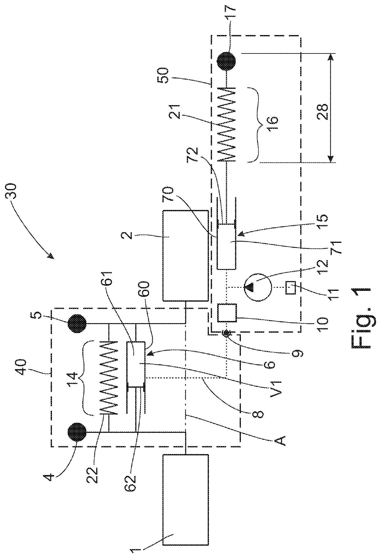
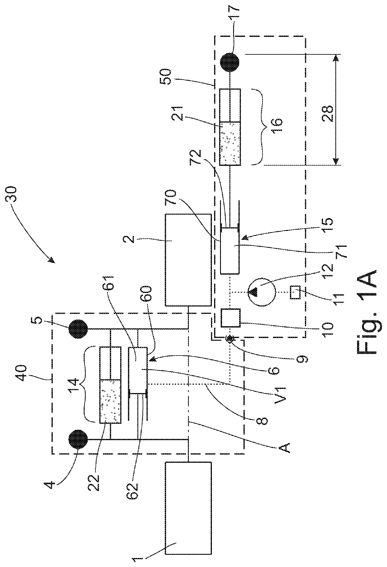
[0023]FIG. 1 shows a torsional vibration damping arrangement 30 which is installed between a drive unit 1 and a transmission unit 2. In the present case, the torsional vibration damping arrangement 30 principally comprises a rotational mass arrangement 40 which is rotatable around the rotational axis A and a damping arrangement 50 which is not rotatable around rotational axis A but, rather, is positioned in a stationary manner, for example, in a trunk compartment of a motor vehicle, not shown. The rotational mass arrangement 40 in the present instance comprises a primary inertia element 4 and a secondary inertia element 5 which are both rotatable relative to one another opposite the working direction of a displacer unit 6 and a fixed stiffness 14 connected in parallel with the latter. The fixed stiffness 14 in FIG. 1 is an energy storage 22 formed by an elastically deformable element 22 such as a steel spring; while FIG. 1A shows the energy storage as a pneumatically compressible el...


PUM


Abstract

A torsional vibration damping arrangement for a drivetrain of a vehicle comprises a rotational mass arrangement which is rotatable around a rotational axis A and a damping arrangement fixed with respect to rotation relative to the rotational axis A. A displacer unit is operatively connected to the primary inertia element on the one side and to the secondary inertia element on the other side. The damping arrangement includes a slave cylinder with a working chamber having a volume V2, and the working chamber of the slave cylinder is operatively connected to the working chamber of the displacer unit. The damping arrangement includes a stiffness arrangement and a damper mass, and the slave cylinder of the damping arrangement is operatively connected to the damper mass by a stiffness arrangement.

Description

PRIORITY CLAIM[0001]This is a U.S. national stage of application No. PCT / EP2016 / 081658, filed on Dec. 19, 2016. Priority is claimed on the following application: Country: Germany, Application No.: 10 2016 200 888.9, filed: Jan. 22, 2016, the content of which is / are incorporated in its entirety herein by reference.FIELD OF THE INVENTION[0002]The present invention is directed to a torsional vibration damping arrangement for a drivetrain of a vehicle, comprising a primary side to be driven in rotation around a rotational axis and a secondary side which is coupled with the primary side via a working medium for rotation around the rotational axis and for relative rotation with respect to one another.BACKGROUND OF THE INVENTION[0003]A torsional vibration damping arrangement of this kind is known from US published application US-2010-0090382-A1. This known torsional vibration damping arrangement has a primary side and a secondary side which is coupled with the primary side via a damper flu...

Claims


Application Information

Patent Timeline
Patent Type & Authority Patents(United States)
IPC IPC(8): F16F15/16F16F15/02F16F15/20F16F7/104
CPCF16F15/162F16F15/20F16F15/161F16F7/104F16F15/02
Inventor ORLAMÜNDER, ANDREASLORENZ, DANIELDÖGEL, THOMASSIEMENS, KYRILLWACK, ERWINDIECKHOFF, TOBIASTERWART, MARKUSREISCH, MATTHIASARZNER, MATTHIAS
Owner ZF FRIEDRICHSHAFEN AG
Why Eureka
Try Eureka