
Imaging lens and imaging apparatus

a technology of imaging apparatus and lens, applied in the direction of optics, instruments, optical elements, etc., can solve the problem of product outer diameter, and achieve the effect of small fluctuation of angle of view and favorable performan

Active Publication Date: 2020-06-23
FUJIFILM CORP
View PDF18 Cites 0 Cited by
  • Summary
  • Abstract
  • Description
  • Claims
  • Application Information

AI Technical Summary

Benefits of technology

[0004]In recent years, the camera is generally configured by combining an imaging lens and an imaging element such as a charge coupled device (CCD) or a complementary metal oxide semiconductor (CMOS). In such a configuration, there is a demand for an imaging lens having a small angle of incidence of the principal ray onto the image plane at the maximum angle of view regardless of the imaging distance, for the purpose of suppressing a decrease in amount of peripheral light and the like. Further, in the above-mentioned camera, there is also a demand for small fluctuation in angle of view caused by focusing. Furthermore, in consideration of the standard of the mount portion that joins the camera body and the imaging lens, there is a demand for an imaging lens that has a configuration capable of making the product outer diameter small.
[0006]The present invention has been made in consideration of the above-mentioned situations, and its object is to provide an imaging lens, which can be configured to have a small angle of incidence of the principal ray onto the image plane at the maximum angle of view regardless of an imaging distance, small fluctuation in angle of view caused by focusing, and a small product outer diameter and to have favorable performance, and an imaging apparatus comprising the imaging lens.
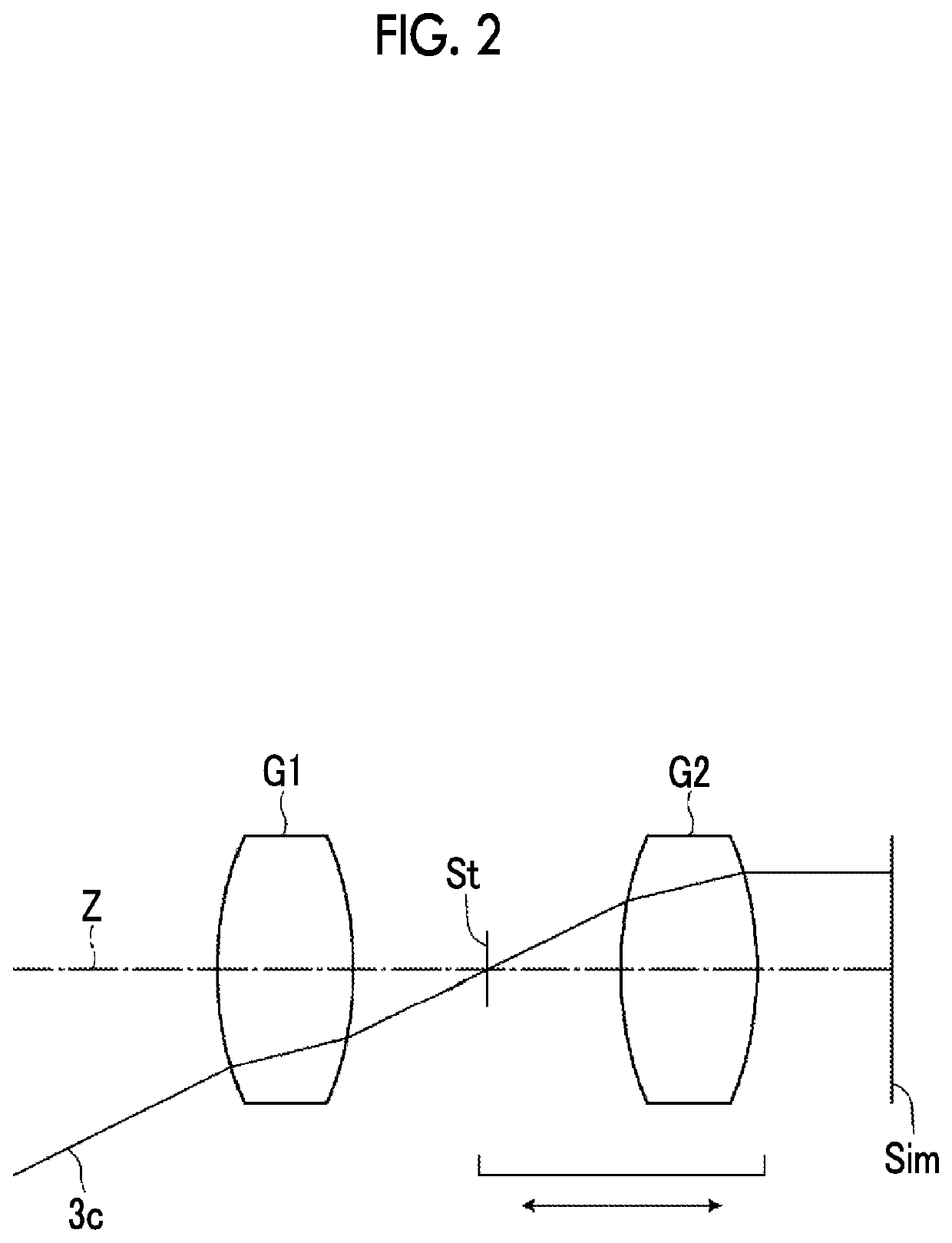
[0019]According to the present invention, the lens system consists of, in order from the object side, the first lens group, the aperture stop, the second lens group having a positive refractive power. In the lens system, by appropriately setting the behavior during focusing and satisfying the predetermined conditional expressions, it is possible to provide an imaging lens, which can be configured to have a small angle of incidence of the principal ray onto the image plane at the maximum angle of view regardless of an imaging distance, small fluctuation in angle of view caused by focusing, and a small product outer diameter and to have favorable performance, and an imaging apparatus comprising the imaging lens.

Problems solved by technology

However, it is difficult for the lens system described in JP2003-202493A and JP1997-43512A (JP-H09-43512A) to reduce the product outer diameter of the imaging lens.

Method used


Image

  • Imaging lens and imaging apparatus
  • Imaging lens and imaging apparatus
  • Imaging lens and imaging apparatus

Examples


example 1

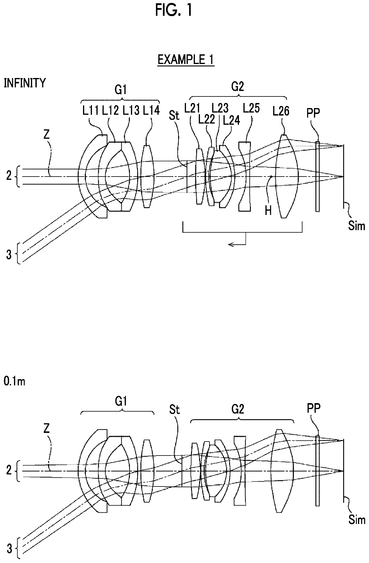
[0073]FIG. 1 shows a cross-sectional view of an imaging lens of Example 1, and an illustration method thereof is as described above. Therefore, repeated description is partially omitted herein. The imaging lens of Example 1 consists of, in order from the object side to the image side, a first lens group G1 having a negative refractive power, an aperture stop St, and a second lens group G2 having a positive refractive power. The first lens group G1 remains stationary with respect to the image plane Sim during focusing from a distant object to a close-range object, and the aperture stop St and the second lens group G2 integrally move toward the object side. The first lens group G1 consists of four lenses L11 to L14 in order from the object side to the image side, and the second lens group G2 consists of six lenses L21 to L26 in order from the object side to the image side.

[0074]Table 1 shows basic lens data of the imaging lens of Example 1, Table 2 shows specification and variable sur...

example 2

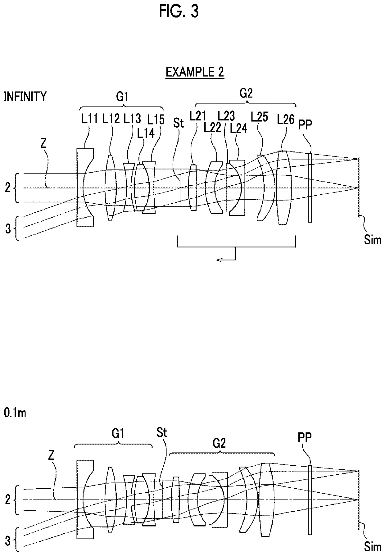
[0089]FIG. 3 is a cross-sectional view of an imaging lens of Example 2. The imaging lens of Example 2 consists of, in order from the object side to the image side, a first lens group G1 having a negative refractive power, an aperture stop St, and a second lens group G2 having a positive refractive power. The first lens group G1 remains stationary with respect to the image plane Sim during focusing from a distant object to a close-range object, and the aperture stop St and the second lens group G2 integrally move toward the object side. The first lens group G1 consists of five lenses L11 to L15 in order from the object side to the image side, and the second lens group G2 consists of six lenses L21 to L26 in order from the object side to the image side. Table 4 shows basic lens data of the imaging lens of Example 2, Table 5 shows specification and variable surface distances, Table 6 shows aspheric surface coefficients, and FIG. 8 shows aberration diagrams.

[0090]

TABLE 4Example 2Surface...

example 3

[0093]FIG. 4 is a cross-sectional view of an imaging lens of Example 3. The imaging lens of Example 3 consists of, in order from the object side to the image side, a first lens group G1 having a positive refractive power, an aperture stop St, and a second lens group G2 having a positive refractive power. The first lens group G1 remains stationary with respect to the image plane Sim during focusing from a distant object to a close-range object, and the aperture stop St and the second lens group G2 integrally move toward the object side. The first lens group G1 consists of seven lenses L11 to L17 in order from the object side to the image side, and the second lens group G2 consists of six lenses L21 to L26 in order from the object side to the image side. Table 7 shows basic lens data of the imaging lens of Example 3, Table 8 shows specification and variable surface distances, Table 9 shows aspheric surface coefficients, and FIG. 9 shows aberration diagrams.

[0094]

TABLE 7Example 3Surfac...


PUM


Abstract

The imaging lens consists of, in order from the object side, a first lens group, an aperture stop, a second lens group having a positive refractive power. During focusing from a distant object to a close-range object, the first lens group remains stationary, and the aperture stop and the second lens group integrally move to the object side. The imaging lens satisfies predetermined conditional expressions relating to a focal length of the whole system, a focal length of the first lens group, a principal point position of the second lens group, a focal length of the second lens group, a back focal length, and the like.

Description

CROSS-REFERENCE TO RELATED APPLICATIONS[0001]The present application claims priority under 35 U.S.C. § 119 to Japanese Patent Application No. 2017-178515, filed on Sep. 19, 2017. The above application is hereby expressly incorporated by reference, in its entirety, into the present application.BACKGROUND OF THE INVENTION1. Field of the Invention[0002]The present invention relates to an imaging lens and an imaging apparatus. In particular, the present invention relates to an imaging lens, which is suitable for a factory automation (FA) camera, a machine vision (MV) camera, a digital camera, a surveillance camera, an on-board camera, a cinema camera, and the like, and an imaging apparatus comprising the imaging lens.2. Description of the Related Art[0003]In MV cameras and the like, an imaging lens having a focusing function has been used. As an imaging lens that has a focusing function conventionally known, for example, there are lenses described in JP2003-202493A, JP1997-43512A (JP-H0...

Claims


Application Information

Patent Timeline
Patent Type & Authority Patents(United States)
IPC IPC(8): G02B13/22G02B13/04G02B15/14G02B27/00G02B13/00
CPCG02B13/0045G02B13/22G02B15/14G02B27/0025G02B13/04G02B15/1425
Inventor KUNUGISE, TAKASHIOKADA, KAZUYOSHI
Owner FUJIFILM CORP
Learn More