Set of extruded shapes for glass balcony railings and enclosures

a technology of glass balcony railings and enclosures, which is applied in the direction of handrails, balconies, building components, etc., can solve the problems of preventing the construction of glass walls having a greater height, low height enclosures, and low height not meeting

Active Publication Date: 2020-06-30
MAZZOLA VERNENGO PABLO REMO
View PDF11 Cites 4 Cited by
  • Summary
  • Abstract
  • Description
  • Claims
  • Application Information

AI Technical Summary

Benefits of technology

[0010]The main object of the present invention is a set of extruded shapes allowing fitting glass panels with a height up to 3 meters for the construction of transparent railings, dividing walls, etc., without the need to use of columns or intermediate uprights or reinforcing posts, providing an effective protection or a shield from the action of the wind while achieving an unrestricted view through said panels.

Problems solved by technology

The above said implies that if we do not place uprights, columns or other structural components, the anchoring of the glass panels is basically limited to fixing them to the floor, such as a balcony floor, slab, etc. inside a shape or shapes component into which lodges each glass plate: This limits the height of the crowning of the glass panels, resulting in very low height enclosures, preventing the construction of glass walls having a greater height, such as, for instance, up to 3 meters.
Indeed, for security reasons, balcony railings must have a minimum height; while low height glass walls offers no means of protection against the action of the wind, hence their low height does not fulfil this purpose.
Additionally, considering the use of glass panels as spatial dividers (e.g.) separating grandstands from the actual playing field, the use of thick laminated glass panels is ideal because it allows the onlookers a view of the playing field without obstructions or limitations, while said glass panels for security reasons do not provide any possible means to climb over the separation barrier and perform an illegal entry into the playing field.
Its anchoring to the floor by means of known traditional means does not allow performing this construction unless structural reinforcing means are employed, such as columns or the like, obstructing the view.

Method used


Image

  • Set of extruded shapes for glass balcony railings and enclosures
  • Set of extruded shapes for glass balcony railings and enclosures
  • Set of extruded shapes for glass balcony railings and enclosures

Examples


Embodiment Construction

[0016]For the purposes of exemplifying a preferred embodiment of the present invention, the following drawings illustrating it are attached in support of the description thereof given below, this embodiment having to be interpreted as one of the many possible constructions of the invention, hence it is not appropriate to assign any limiting value to it, including within the scope of protection of the invention the possible equivalent means; the amplitude of the present invention being determined by its first claim.

[0017]Likewise, in these Figures, the same references identify equal or equivalent means equal and / or equivalent.

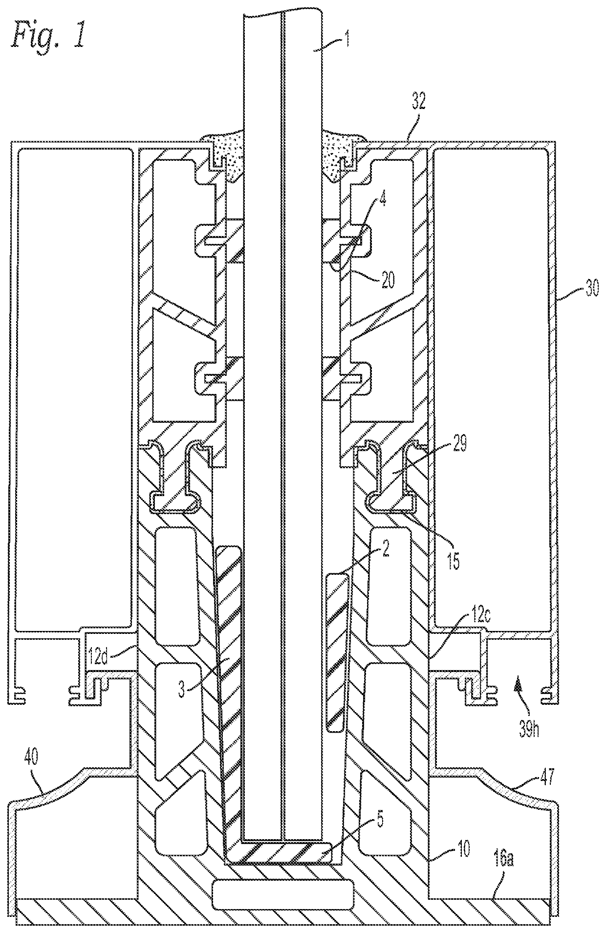
[0018]FIG. 1 shows a cross section of the assembled shapes with a glass plate inserted and retained within said assembly;

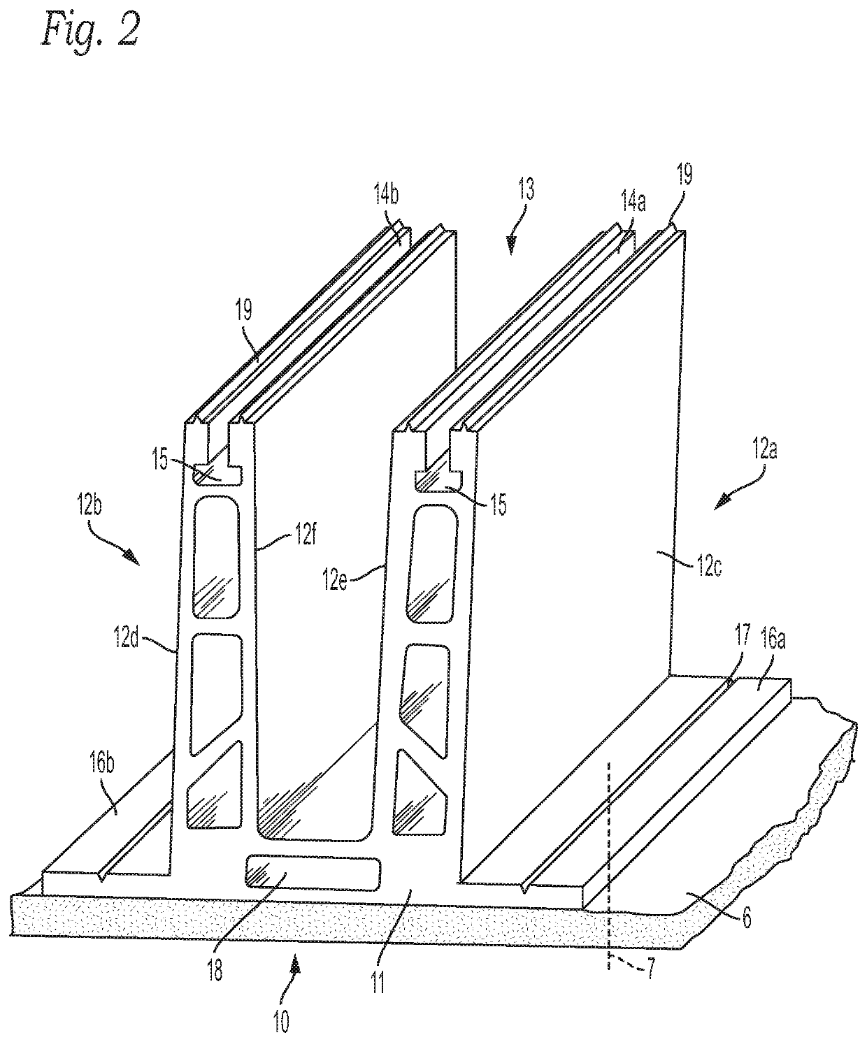
[0019]FIG. 2 shows a front / lateral perspective to the first shape;

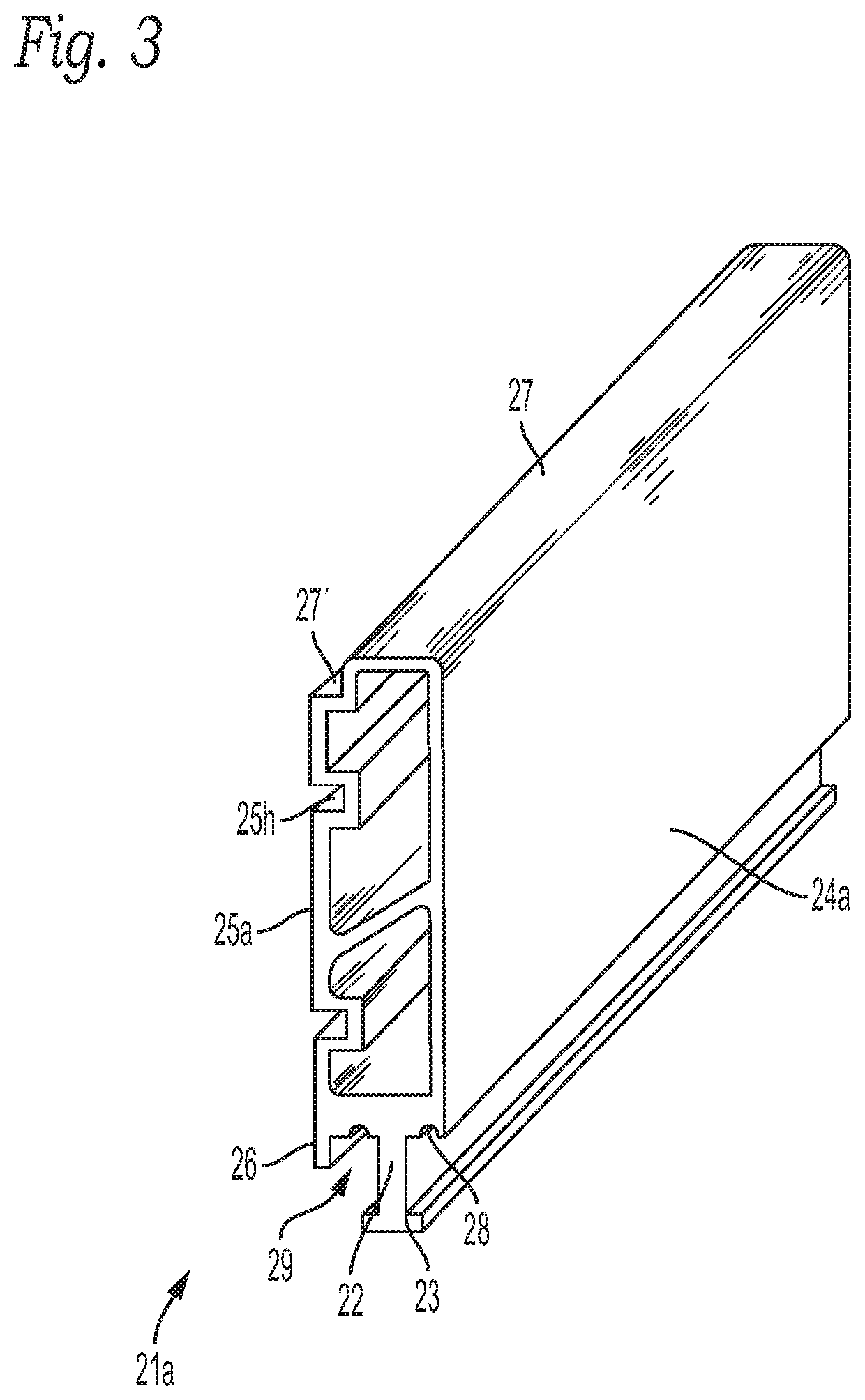
[0020]FIG. 3 illustrates a front / perspective of the second right side shape:

[0021]FIG. 4 illustrates a front / perspective of the second left side shape

[0022]FIG. 5 illustrates a ...


PUM


Abstract

Set of shapes for retaining a glass plate, including a first shape (10) having a base plate (11) from which project columns (12a, 12b) between which define a longitudinal channel (13), having at the upper end of each column a longitudinal groove (14, 15).
Second shapes (20) arranged vertically aligned on each column of the first shape, this second shape having at its lower end an appendix (22) complementary to the groove (14, 15); presenting the upper end of the second shape on its edge of its internal face a longitudinal recess (27′) that determines the means of seating and securing a third shape (30).
Said third shape each has an upper surface (32, 32′) that sits on the upper end (27) of the second shape, with a longitudinal fold complementary to the longitudinal recess (27′) of the second shape and within which it sits in retention. The upper surface (32, 32′) projects downwards attached to the external surface (12, 24) of (10, 20) covering the joint between them.
The lower end of each third shape forms at the lower end a longitudinal “L” seat (38) turned towards the external face of each column of the first shape.
A fourth shape (40) is placed on each side of the corresponding column of the first shape and has a substantially horizontal wing (42) at the free end of which has a longitudinal projection (43) that seats in connection with the longitudinal recess seat (27′).) of the third shape: said horizontal wing (42) is continued by a section of shape (45) partially attached against the external face of the respective column up to where a continuous concave surface (47) projects facing a hosted light source in (39h).

Description

FIELD OF INVENTION[0001]The invention relates to the enclosure and balcony railing construction formed by transparent or translucent plates, such as tempered or laminated glass, capable of offering a decorative view without obstructions achieving a height at the crowning of the enclosure between 80 to 300 cms.BACKGROUND TO THE INVENTION[0002]Using laminated and / or tempered glass panels for balconies, terraces, swimming pools, solariums enclosures and room dividers is a well-known resource employed by professionals in the construction and decoration arts.[0003]Said enclosures advantageously prevents or mitigate the passage of wind while providing at the same a decorative environment, allowing a panoramic vision of the surroundings. For said aesthetics reasons, said enclosures formed by adjacent glass plates should employ as little as possible structural components such as uprights, which may mar said view and the decorative aspect of said enclosures.[0004]The above said implies that ...

Claims


Application Information

Patent Timeline
Patent Type & Authority Patents(United States)
IPC IPC(8): E04B1/00E04F11/18
CPCE04B1/003E04F11/1853E04F11/1804E04F2011/1868
Inventor MAZZOLA VERNENGO, PABLO REMO
Owner MAZZOLA VERNENGO PABLO REMO
Why Eureka
Try Eureka