Mechanism for swinging and steering support leg for pavement milling machine

a technology of supporting leg and pavement milling machine, which is applied in the direction of roads, highway maintenance, transportation and packaging, etc., can solve the problems of increasing cost, tire or track cannot be steered, and additional devices are required, so as to facilitate the swinging and steering control operation and reduce the cost

Active Publication Date: 2020-07-14
DYNAPAC CHINA COMPACTION & PAVING EQUIP
View PDF13 Cites 5 Cited by
  • Summary
  • Abstract
  • Description
  • Claims
  • Application Information

AI Technical Summary

Benefits of technology

[0006]The invention aims to provide a mechanism for swinging and steering a support leg for a pavement milling machine, so as to achieve the swinging and steering of the support leg of the pavement milling machine without increasing an additional device.
[0012]With the mechanism for swinging and steering the support leg for the pavement milling machine of the present invention, the swinging and steering functions are achieved through a five-bar mechanism, thereby reducing the cost, and the individually controlling of the swinging and the steering can be achieved by controlling the swing oil cylinder and the steering oil cylinder, facilitating the swinging and steering control operations.

Problems solved by technology

At present, the existing support leg swing is achieved by rotating around a pin roll fixed on the milling machine frame by a certain angle, however, at this time a tire or the track is also rotated by the corresponding angle following the swing of the support leg, so an additional reversing valve needs to be installed to switch oil inlet and outlet lines to change the direction of the tire or the track, which increases the cost.
An alternative method for ensuring that the advancing direction of the tire or the track is unchanged before and after swinging through a four-bar mechanism, but its defect is that the tire or the track cannot be steered and an additional device is required to control the steering.

Method used


Image

  • Mechanism for swinging and steering support leg for pavement milling machine
  • Mechanism for swinging and steering support leg for pavement milling machine
  • Mechanism for swinging and steering support leg for pavement milling machine

Examples


Embodiment Construction

[0018]Embodiments of the present invention will be further described in detail with reference to the accompanying drawings, but are not to be construed as limiting the invention.

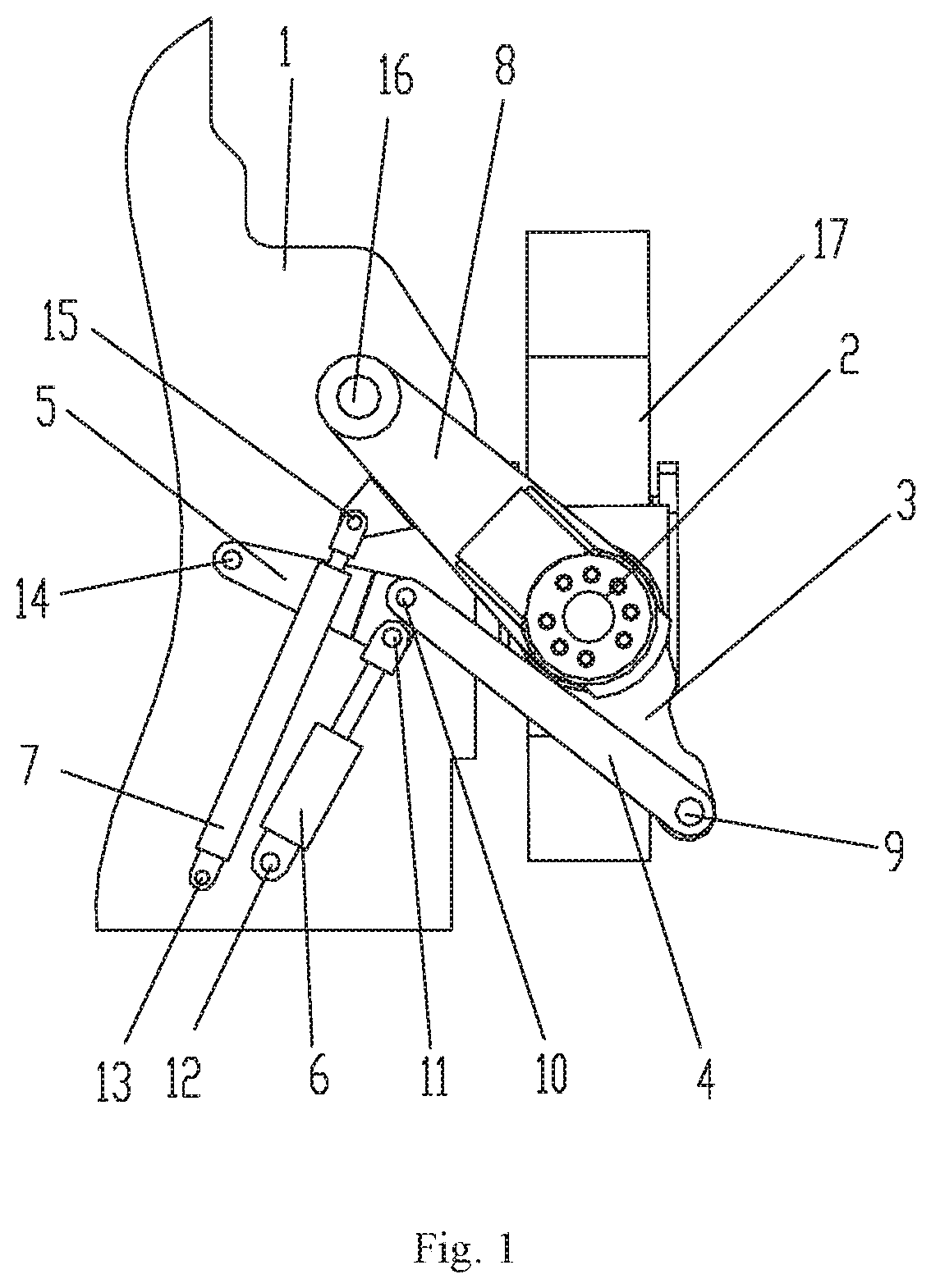
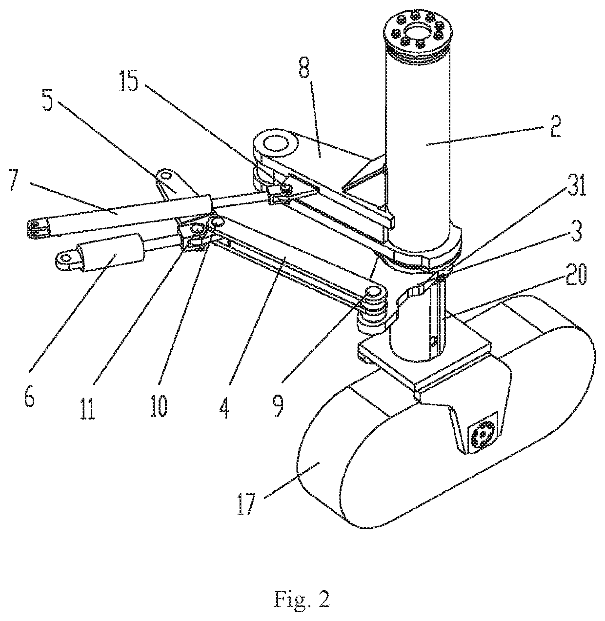
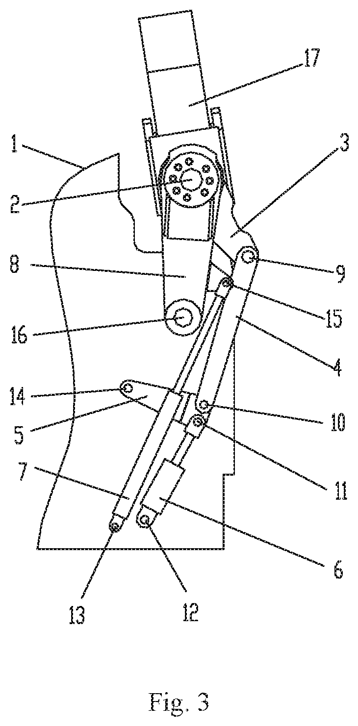
[0019]See FIG. 1 to FIG. 4, the mechanism for swinging and steering the support leg for the pavement milling machine in the present invention comprises a milling machine frame 1, a swing rod 8, a swing oil cylinder 7, a steering rod 3, a first guiding rod 4, a second guiding rod 5 and a steering oil cylinder 6.

[0020]The support leg of the pavement milling machine comprises a support leg exterior sleeve 2 and a support leg interior sleeve 20, a track 17 is installed below the support leg interior sleeve 20, the support leg exterior sleeve 2 is sleeved onto the support leg interior sleeve 20, and the support leg interior sleeve 20 can rotate relative to the support leg exterior sleeve 2, so as to achieve the steering of the track 17.

[0021]One end of the swing rod 8 is hinged to the milling machine frame 1 thro...


PUM


Abstract

A mechanism for swinging and steering a support leg for a pavement milling machine is provided having a milling machine frame, a swing rod, a steering rod, a first guiding rod and a second guiding rod, the support leg includes a support leg exterior sleeve and a interior sleeve, the support leg exterior sleeve is sleeved onto the support leg interior sleeve, the support leg interior sleeve rotates relative to the exterior sleeve; one end of the swing rod is hinged to the milling machine frame, and the other end is fixedly connected to the exterior sleeve; one end of the second guiding rod is hinged to the milling machine frame, the other end is hinged to one end of the first guiding rod, the other end of the first guiding rod is hinged to one end of the steering rod, and the other end of the steering rod is connected to the support leg interior sleeve.

Description

CROSS REFERENCE TO RELATED APPLICATIONS[0001]This application is a national stage application of International Application No. PCT / CN2017 / 076579, filed Mar. 14, 2017, which claims the benefit of and priority to Chinese Patent Application No. 201610150576.5, filed Mar. 16, 2016, the entire contents of each of which are hereby incorporated by reference herein.TECHNICAL FIELD[0002]The present invention relates to the field of construction machinery, and in particular, the present invention relates to a mechanism for swinging and steering a support leg for a pavement milling machine.BACKGROUND OF THE INVENTION[0003]The pavement milling machine is one of the main machines of pavement maintenance construction machinery, and it is a most economical modem maintenance method for milling damaged old paving layers by using the pavement milling machine, and laying new surface layers. Due to its advantages such as its high working efficiency, simple construction process, easily controllable mill...

Claims


Application Information

Patent Timeline
Patent Type & Authority Patents(United States)
IPC IPC(8): B62D11/20B62D55/084E01C23/088
CPCB62D55/084B62D11/20E01C23/088B60G3/01B60G2300/09B60G2300/32
Inventor ZHANG, BIAOCHEN, JIXUEXU, TINGJIAN
Owner DYNAPAC CHINA COMPACTION & PAVING EQUIP
Why Eureka
Try Eureka