Indication system for a quick coupler assembly

a coupler assembly and indicator system technology, applied in the direction of vehicles, constructions, tractors, etc., can solve the problems of cumbersome visual observation of the state of the piston pin, prone to errors, and sometimes unreliabl

Active Publication Date: 2020-07-14
CATEPILLAR SARL
View PDF20 Cites 9 Cited by
  • Summary
  • Abstract
  • Description
  • Claims
  • Application Information

AI Technical Summary

Problems solved by technology

However, visually observing the state of the piston pins may be a cumbersome process, prone to errors, and sometimes unreliable.

Method used


Image

  • Indication system for a quick coupler assembly
  • Indication system for a quick coupler assembly
  • Indication system for a quick coupler assembly

Examples


Embodiment Construction

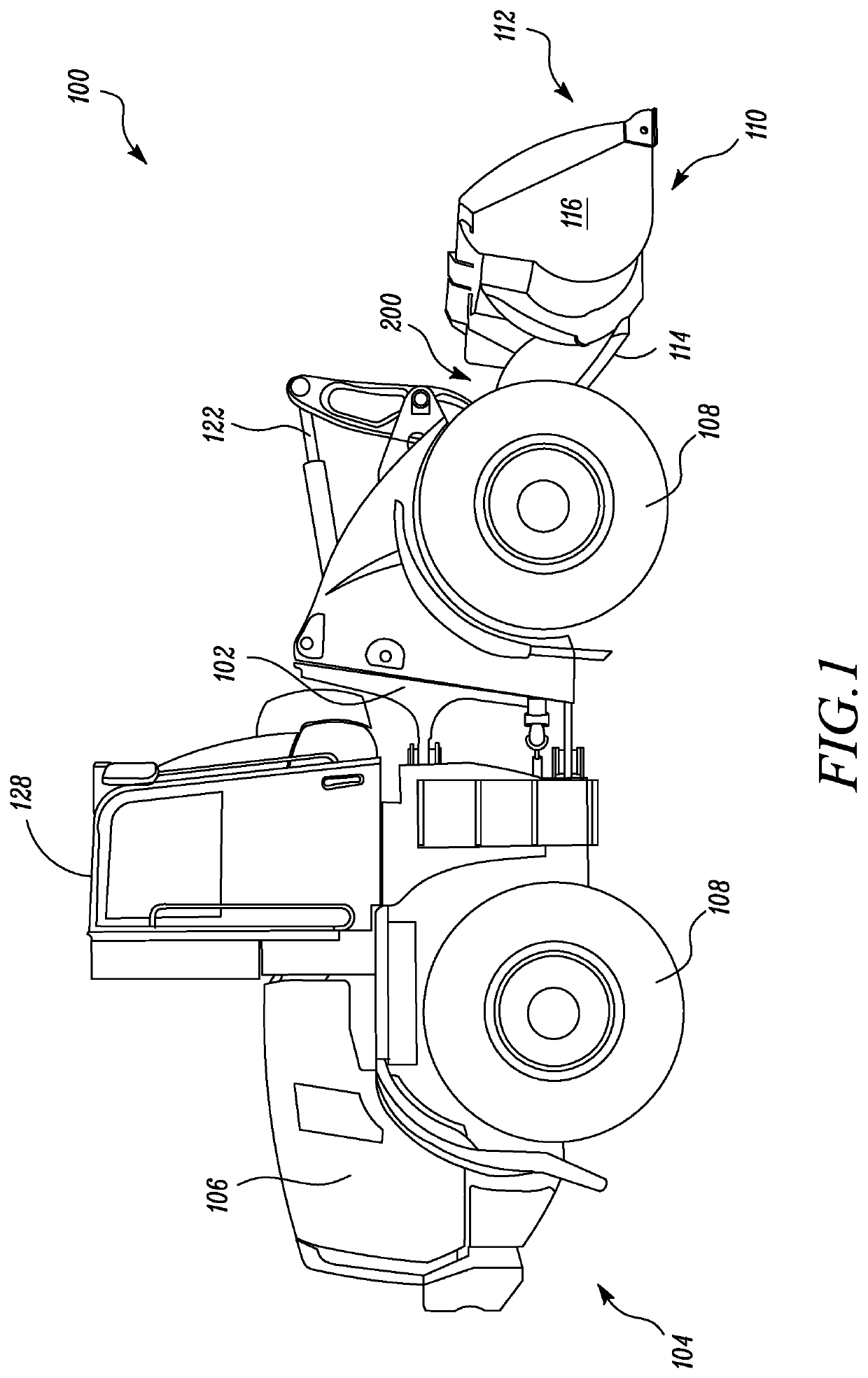
[0011]Wherever possible, the same reference numbers will be used throughout the drawings to refer to the same or the like parts. Referring to FIG. 1, an exemplary machine 100 is illustrated. More specifically, the machine 100 is a compact wheel loader. Alternatively, the machine 100 may be any machine including, but not limited to, a skid steer loader, a backhoe loader, an excavator, a shovel, a dozer, a mining truck, an articulated truck, a track type tractor, a forklift, and a crane. The machine 100 may be any machine known in the art associated with industries including, but not limited to, agriculture, transportation, mining, construction, forestry, and material handling.

[0012]The machine 100 includes a frame 102. A power source (not shown) is provided at a rear section 104 of the machine 100. More particularly, the power source is provided within an enclosure 106. The power source may be any power source known in the art, such as, an internal combustion engine, an electric moto...


PUM


Abstract

An indication system associated with a coupler assembly includes a sensing element affixed to the coupler assembly, and an indicator assembly coupled to the sensing element. The sensing element is arranged and positioned proximate to a hydraulic assembly of the coupler assembly. The sensing element is configured to generate a signal indicative of an extension of a piston pin of the hydraulic assembly. The indicator assembly is configured to receive the signal indicative of the extension of the piston pin, and determine if the piston pin is in an extended state based on the received signal.

Description

TECHNICAL FIELD[0001]The present disclosure relates to an indication system, and more particularly to the indication system associated with a coupler assembly of a machine.BACKGROUND[0002]A linkage assembly of a machine may interchangeably receive different implements or worktools, such as, blades or buckets, based on a type of operation being performed thereby. A hydraulic assembly is generally used for the engagement between the worktool and the linkage assembly. More particularly, piston pins associated with the hydraulic assembly are configured to engage the linkage assembly and the worktool. An extension of the piston pin is important to determine whether the worktool is in positive engagement with the linkage assembly so that the worktool does not fall off the machine during operation. Therefore, an operator of the machine may verify the extended state of the piston pins by visually inspecting the piston pins while seated within an operator cabin. However, visually observing t...

Claims


Application Information

Patent Timeline
Patent Type & Authority Patents(United States)
IPC IPC(8): E02F9/26E02F3/36
CPCE02F3/3663E02F9/264E02F9/26E02F3/3609E02F3/3659B62D49/065E02F3/3636F15B15/2815
Inventor WEBB, ADRIANSUDALE, STEVEN
Owner CATEPILLAR SARL
Why Eureka
Try Eureka