Window mountable illuminated sign assembly

a technology of illuminated signs and windows, applied in the field of vehicle safety signs, can solve the problems of not including structural or functional features, failure to attract motorists' attention, and the failure of devices to incorporate a variety of options for electrically charging the signs, so as to achieve effective and efficient communication of messages

Active Publication Date: 2020-07-14
ST JOHN SUSAN
View PDF10 Cites 0 Cited by
  • Summary
  • Abstract
  • Description
  • Claims
  • Application Information

AI Technical Summary

Benefits of technology

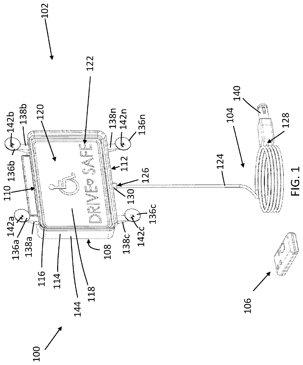
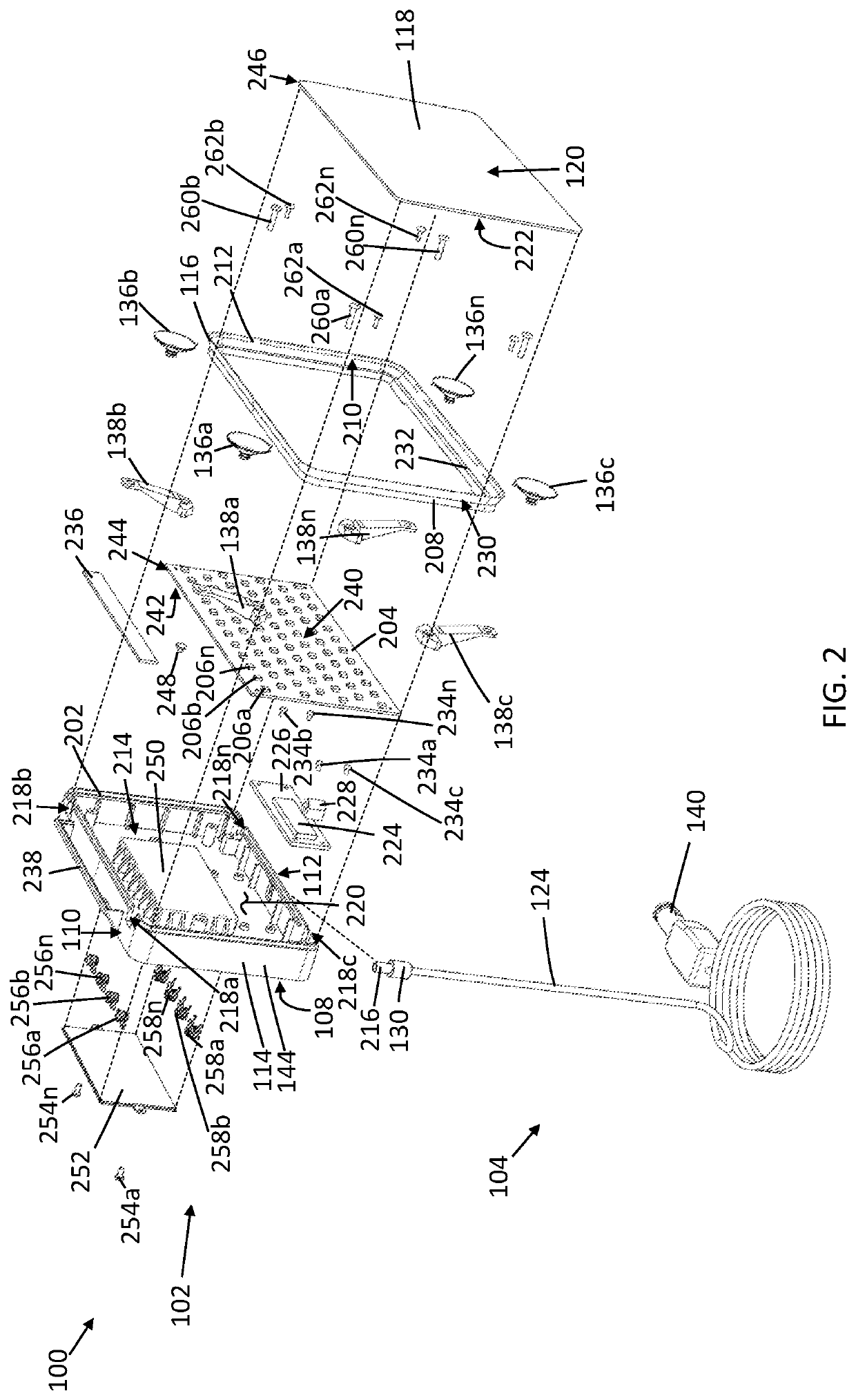
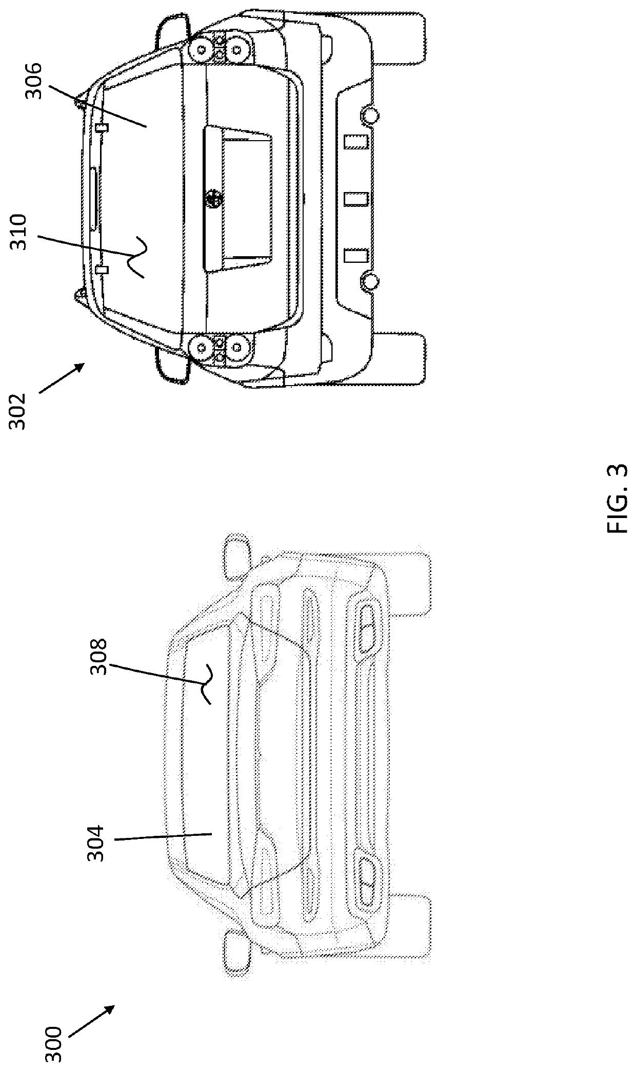
[0008]The invention provides a window mountable illuminated sign assembly that overcomes the hereinafore-mentioned disadvantages of the heretofore-known devices and methods of this general type and that effectively and efficiently communicates messages to other motorists on the road utilizing noticeable illumination techniques as well as a remote control capable of controlling various aspects and features of the sign, while simultaneously enabling the user to electrically charge the sign through a variety of options.

Problems solved by technology

However, because driving is a part of everyday life for the typical person, most motorists often become inattentive and robotic, and therefore, these simple vehicle-mounted safety signs often go unnoticed and fail to attract a motorist's attention.
Problematically, however, these devices fail to include structural or functional features to focus the light facing outwardly against an automobile's rear window, thereby providing a more enhanced display.
Moreover, these devices do not incorporate a variety of options to electrically charge the sign, for example, solar panel, batteries, and a rechargeable lithium battery.
Additionally, these devices do not utilize motion sensors or brake-activation to power, activate, or illuminate the sign.

Method used


Image

  • Window mountable illuminated sign assembly
  • Window mountable illuminated sign assembly
  • Window mountable illuminated sign assembly

Examples


Embodiment Construction

[0039]While the specification concludes with claims defining the features of the invention that are regarded as novel, it is believed that the invention will be better understood from a consideration of the following description in conjunction with the drawing figures, in which like reference numerals are carried forward. It is to be understood that the disclosed embodiments are merely exemplary of the invention, which can be embodied in various forms. Therefore, specific structural and functional details disclosed herein are not to be interpreted as limiting, but merely as a basis for future claims and as a representative basis for teaching one of ordinary skill in the art to variously employ the present invention in virtually any appropriately detailed structure. Further, the terms and phrases used herein are not intended to be limiting; but rather, to provide an understandable description of the invention. It is believed that the invention will be better understood from a conside...


PUM


Abstract

A window mountable illuminated sign assembly configured to removably couple to a vehicle window and that comprises a sign housing coupled to a translucent front panel defining an interior cavity. The interior cavity holding an LED panel including a plurality of LED lights disposed in a tightly spaced configuration with respect to one another. The translucent front panel coupled to and surrounded by a flange that extends outwardly from the front surface of the translucent front panel and is capable of flexing and deforming. The sign assembly also comprises a plurality of suction cup fasteners individually and independently capable of flexing and deforming. The assembly further includes a variety of power options as well as a remote control operably configured to communicate signals that control various aspects and features of the sign assembly.

Description

CROSS-REFERENCE TO RELATED APPLICATION[0001]This application claims priority to U.S. Provisional Patent Application No. 62 / 611,180 filed Dec. 28, 2017, the entirety of which is incorporated by reference.FIELD OF THE INVENTION[0002]The present invention relates generally to vehicle safety signs, and, more particularly, relates to a window mountable illuminated sign assembly.BACKGROUND OF THE INVENTION[0003]Typically, vehicle-mounted safety signs are used by a variety of different users in order to inform and notify near-by motorists of additional safety precautions which should be taken because they personally affect the user. These signs are often mounted on the rear interior or exterior windshield of a vehicle to display the message to other motorists, emergency personnel, and to the general public. The use of these signs can be particularly beneficial for users who are carrying certain passengers or have a particular condition which would otherwise be unknown to others. Usually, a...

Claims


Application Information

Patent Timeline
Patent Type & Authority Patents(United States)
IPC IPC(8): G09F13/04B60Q1/26B60Q1/50G09F13/08G09F21/04
CPCB60Q1/503B60Q1/268G09F21/04G09F13/08B60Q1/2696G09F13/0413G09F2013/044B60Q2900/30G09F13/044
Inventor ST. JOHN, SUSAN
Owner ST JOHN SUSAN
Why Eureka
Try Eureka