Driving apparatus and driving signal generating method thereof
- Summary
- Abstract
- Description
- Claims
- Application Information
AI Technical Summary
Benefits of technology
Problems solved by technology
Method used
Image
Examples
Embodiment Construction
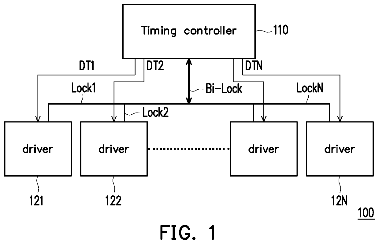
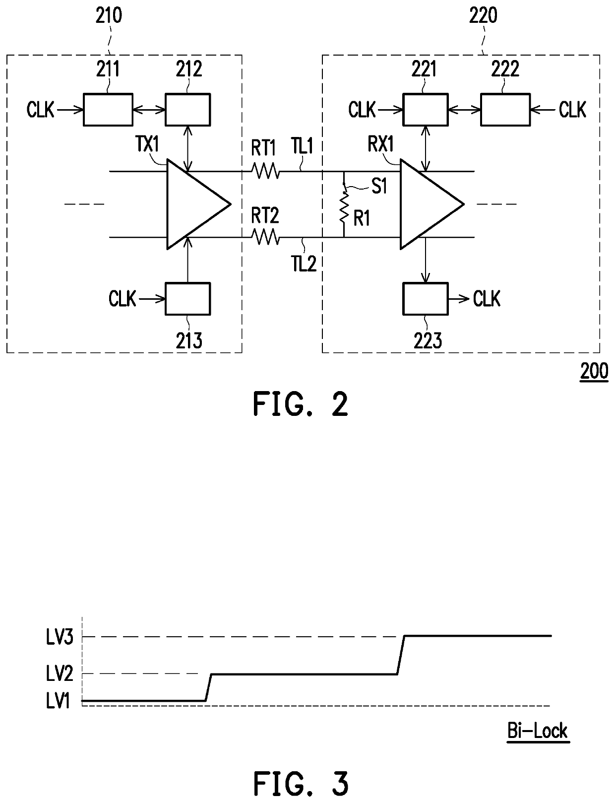
[0018]Please refer to FIG. 1. FIG. 1 is a schematic diagram of a driving apparatus according to an embodiment of the disclosure. A driving apparatus 100 is adapted for a display, and the driving apparatus 100 includes a timing controller 110 and one or more drivers 121˜12N. The timing controller 110 provides an output differential voltage and has a pre-emphasis circuit. The timing controller 110 is coupled to the drivers 121˜12N, receives the lock signals Lock1˜LockN respectively generated by the drivers 121˜12N, and generates a bi-direction lock signal Bi-Lock according to the lock signals Lock1˜LockN. The timing controller 110 transmits the differential signal pairs DT1˜DTN to the drivers 121˜12N, respectively. Please refer to FIG. 1 and FIG. 2, wherein FIG. 2 is a block diagram showing the circuit structure of a driving apparatus according to an embodiment of the disclosure.
[0019]In FIG. 2, a driving apparatus 200 includes a timing controller 210, a driver 220, a switch S1, and a...
PUM
 Abstract
Description
Claims
Application Information
 - R&D
- Intellectual Property
- Life Sciences
- Materials
- Tech Scout
- Unparalleled Data Quality
- Higher Quality Content
- 60% Fewer Hallucinations
Browse by: Latest US Patents, China's latest patents, Technical Efficacy Thesaurus, Application Domain, Technology Topic, Popular Technical Reports.
© 2025 PatSnap. All rights reserved.Legal|Privacy policy|Modern Slavery Act Transparency Statement|Sitemap|About US| Contact US: help@patsnap.com


