Implants with groove patterns and soft tissue attachment features

a technology of soft tissue and grooves, applied in the field of orthopaedic implants, can solve the problems of difficult removal of cement substances during surgery, failure of implants, and potential damage to the surrounding anatomy of patients, and achieve the effect of easy installation and removal

Active Publication Date: 2020-07-21
SMED TATD
View PDF58 Cites 2 Cited by
  • Summary
  • Abstract
  • Description
  • Claims
  • Application Information

AI Technical Summary

Benefits of technology

[0014]An advantage of the present invention is the grooves formed in the porous ingrowth material can provide additional friction to keep the implant fixated while bone material grows into the pores to permanently fixate the implant.
[0015]Another advantage is the grooves can be adjusted in many different ways to suit the specific requirements of the implant.
[0016]Yet another advantage is the grooves can also aid tissue attachment to the implant.
[0017]Yet another advantage is the grooves can make the implant easy to install but difficult to remove.

Problems solved by technology

Without being firmly fixated, there is a significant risk that the implant will loosen due to movement of the surrounding anatomy, leading to implant failure and potentially more damage to the surrounding anatomy of the patient.
One known issue with bone cement is that the cement substance is difficult to work with during surgery.
Bone cement has a consistency very similar to normal cement and putties, which makes the bone cement difficult to remove from areas where it is not desired.
If the incorrectly placed bone cement is not adequately removed, the bone cement can damage the anatomy adjacent to the implant during normal movement.
To lessen the risk of this occurring, a surgeon might opt to use less bone cement to temporarily fixate the implant, but lessening the amount of bone cement used presents the risk of not using enough bone cement and not properly fixating the implant.
Such fixation devices can be effective, but can require significantly more operation time and planning to correctly install.
Further, such fixation devices must be fixated in adjacent bone tissue by forcing the fixation devices into the adjacent bone tissue, which can cause damage to the adjacent bone tissue that will need to be surgically repaired.
The filling of the pores with bone material that bonds with the implant is an attractive solution, but the time necessary for sufficient bone ingrowth into the pores is a significant period during which the patient is unable to move the area where the implant is fixated.

Method used


Image

  • Implants with groove patterns and soft tissue attachment features
  • Implants with groove patterns and soft tissue attachment features
  • Implants with groove patterns and soft tissue attachment features

Examples


Embodiment Construction

[0066]The present invention provides implants with grooved features that prevent implant movement, aid tissue attachment, make the implant easier to insert but more difficult to remove, or some combination of the aforementioned features. The present invention also relates to manufacturing methods for such implants.

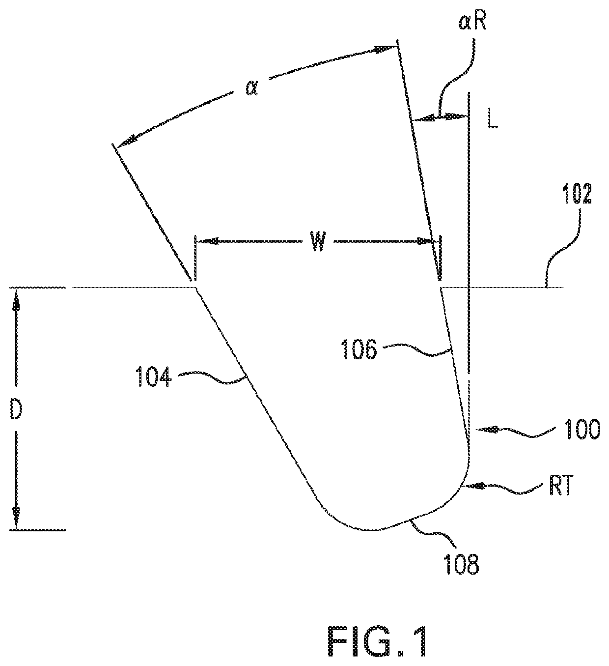
[0067]Referring now to FIG. 1, an example groove 100 is shown that may be included on one or more surfaces 102 of an orthopedic implant. The groove 100 can be one of many grooves located on a porous section of the implant, a solid implant substrate, or a combination of the two. The grooves can have one or more of the following purposes: preventing motion, migration, back-out, tilting, translation, and rotation of the implant; aiding tissue attachment to the implant; and easing implant insertion at an implantation site while increasing the difficulty of implant removal. It should be appreciated that the previously described purposes are exemplary only and grooves can be add...


PUM


Abstract

An orthopaedic implant includes an implant body comprising a biocompatible material and configured to be implanted at an anatomical location, the implant body defining a surface; and a porous material at least one of attached to and integral with the surface of the implant body, the porous material having a plurality of grooves formed therein.

Description

CROSS REFERENCE TO RELATED APPLICATIONS[0001]This is a continuation of PCT application No. PCT / US2015 / 059528, entitled “IMPLANTS WITH GROOVE PATTERNS AND SOFT TISSUE ATTACHMENT FEATURES”, filed Nov. 6, 2015, which is incorporated herein by reference. PCT application No. PCT / US2015 / 059528 is based upon U.S. provisional patent application Ser. No. 62 / 076,901, entitled “IMPLANTS WITH GROOVE PATTERNS AND SOFT TISSUE ATTACHMENT FEATURES”, filed Nov. 7, 2014, which is incorporated herein by reference.BACKGROUND OF THE INVENTION[0002]1. Field of the Invention[0003]The present invention relates to orthopaedic implants.[0004]2. Description of the Related Art[0005]It is well-known to implant orthopaedic implants into a patient's body to attempt to restore musculoskeletal function that the patient has lost or damaged due to injury or disease. Many orthopaedic implants, for example, are meant to replace bone tissue that has failed to heal correctly or cannot be naturally repaired by the patient...

Claims


Application Information

Patent Timeline
Patent Type & Authority Patents(United States)
IPC IPC(8): A61F2/34A61F2/38A61F2/30A61F2/36A61F2/08
CPCA61F2/3662A61F2/30767A61F2/3859A61F2/30771A61F2/367A61F2/0811A61F2/34A61F2/3607A61F2002/3083A61F2002/30828A61F2002/0835A61F2002/0858A61F2002/3092A61F2002/30878A61F2002/30973A61F2002/0864A61F2002/30769A61F2002/30904A61F2002/3093A61F2002/0888A61F2002/3403A61F2002/30011A61F2002/30827A61F2002/0829A61F2002/30537
Inventor JURICK, JOSEPH W.NEBOSKY, PAUL S.STALCUP, GREGORY C.ZIMMERMAN, SARAH L.
Owner SMED TATD
Why Eureka
Try Eureka