Method of manufacturing product with skin

a manufacturing method and skin technology, applied in the field of skin manufacturing methods, can solve the problems of excessive elongation of increased manufacturing steps, and high cost of introducing a dedicated jig for winding the distal end portion of the skin, and achieve the effect of preventing the cutting of the surplus portion

Active Publication Date: 2020-07-21
TOYODA GOSEI CO LTD
View PDF6 Cites 0 Cited by
  • Summary
  • Abstract
  • Description
  • Claims
  • Application Information

AI Technical Summary

Benefits of technology

[0010]According to the manufacturing method, after the shaping process and the trimming process are sequentially performed using the vacuum forming die, the winding process is performed using the vacuum forming die. Thus, a product with skin is manufactured in which the main portion of the skin is covered on the front surface of the base material and the distal end portion of the skin is wound around the back surface of the base material. In this manner, the shaping process, the trimming process and the winding process are performed, in a state where the base material is attached to the vacuum forming die, in other words, using a common vacuum forming die. Therefore, a dedicated jig is unnecessary unlike the case where the winding process is performed using a dedicated jig provided separately from the vacuum forming die. In addition, it is not necessary to transfer the intermediate product subjected to the trimming process from the vacuum forming die to a dedicated jig for winding the distal end portion.
[0013]In this regard, according to the manufacturing method described above, a trim blade capable of reciprocating in the direction along the boundary surface of the base material is used. Then, in the trimming process, the trim blade is moved along the boundary surface toward the side of the surplus portion and pressed against the surplus portion. The surplus portion is cut and the distal end portion remains around the main portion. The distal end portion is constituted only by the portion adjacent to the main portion and orthogonal to the boundary surface. Therefore, the distal end portion has no portion parallel to the boundary surface, the distal end portion becomes shorter by the length of the portion, and it is possible to suppress the excessive elongation of the distal end portion.
[0019]As the length of the cut portion increases, the amount of air to be sucked increases, and the degree of reduction in the force of pulling the surplus portion toward the back surface of the base material increases. The length of the portion to be cut is shorter than that of the portion corresponding to the linear portion at the portion corresponding to the corner portion of the base material in the surplus portion. The cutting of the former portion is performed first by the second trim blade, and the cutting of the latter portion is performed later by the first trim blade. Therefore, the force of pulling the surplus portion toward the back surface of the base material before completion of the cutting of the surplus portion is hard to decrease as compared with the case where the cutting by the first trim blade is performed first and the cutting by the second trim blade is performed later. The surplus portion becomes hard to return to the shape before being pulled by evacuation. Along with this, the distal end portion formed by cutting the surplus portion also approaches the back surface of the base material.
[0022]According to the manufacturing method described above, in the winding process, the distal end portion of the skin is pressed in a direction orthogonal to the boundary surface of the base material by the winding mechanism in a state where the base material is attached to the vacuum forming die. The pressed distal end portion is deformed to be in close contact with the back surface including the boundary surface of the base material. In this way, the distal end portion of the skin is wound around the back surface of the base material without transferring the intermediate product subjected to the trimming process.
[0032]In the trimming process, in a state in which the base material is attached to the remaining portion of the vacuum forming die, the plug is retreated to a position deviated from the movement path of the trim blade. Therefore, the plug is unlikely to hinder the cutting of the surplus portion by the trim blade.

Problems solved by technology

However, in the manufacturing method described in JP-A-2007-160595, it is expensive to introduce the dedicated jig for winding the distal end portion of the skin.
Further, when winding the distal end portion of the skin, there is a need for a step of transferring the intermediate product subjected to the trimming process from the vacuum forming die to the jig, and there is also a problem that the number of manufacturing steps increases accordingly.
Therefore, a dedicated jig is unnecessary unlike the case where the winding process is performed using a dedicated jig provided separately from the vacuum forming die.
The distal end portion becomes longer by the length of the parallel portion, and as a result, the distal end portion may be excessively elongated.
Here, if the cutting of the surplus portion by the first trim blade and the cutting of the surplus portion by the second trim blade adjacent to the first trim blade are performed at the same time, interference between the first trim blade and the second trim blade is unlikely to occur.
However, when the surplus portion is cut while evacuating, air is considerably sucked from the cut portion.
Therefore, the force of pulling the surplus portion toward the back surface of the base material before completion of the cutting of the surplus portion is hard to decrease as compared with the case where the cutting by the first trim blade is performed first and the cutting by the second trim blade is performed later.
Therefore, the plug is unlikely to hinder the cutting of the surplus portion by the trim blade.
Here, as a trim blade, when a blade is used in which a plurality of teeth forming a pointed triangular plate shape are formed in a state of being aligned in a row, and the angle of the blade at the valley portion of each tooth increases as approaching the root part of the tooth, there is a risk as follows.
Accordingly there is a risk of generation of scraps.
It is difficult for scraps to be generated due to tearing off the surplus portion.

Method used


Image

  • Method of manufacturing product with skin
  • Method of manufacturing product with skin
  • Method of manufacturing product with skin

Examples


first embodiment

[0051]Hereinafter, a first embodiment of a method of manufacturing a product with a skin will be described with reference to FIGS. 1A to 9B.

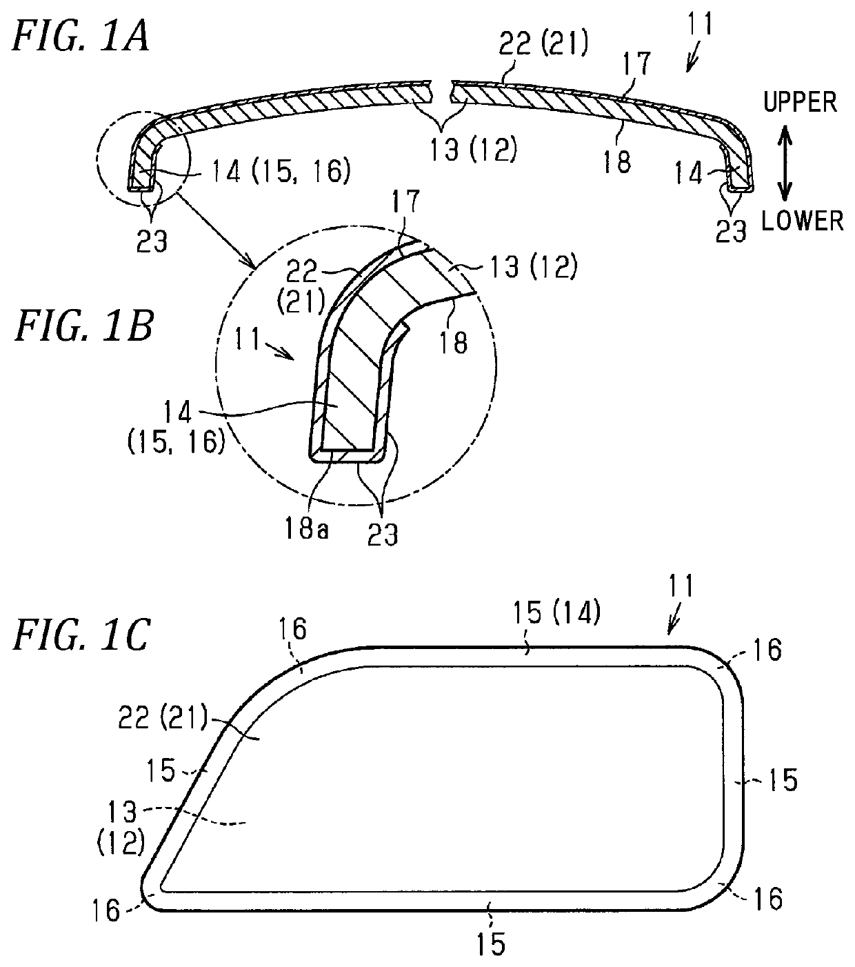
[0052]First, the product with skin manufactured by the manufacturing method of according to the first embodiment will be described. As illustrated in FIGS. 1A to 1C, the product with skin 11 is formed by covering a base material 12 forming a skeleton portion with skin 21 having good decorativeness and hand feeling, and integrating them.

[0053]A main body portion 13 which occupies most of the base material 12 is gently curved such that the central portion bulges more toward the front side (upper side in FIG. 1A) than the peripheral portion. The base material 12 has a peripheral edge portion 14 around the main body portion 13. The peripheral edge portion 14 is curved toward the back surface of the base material 12 (lower side in FIG. 1A). The peripheral edge portion 14 has a plurality of linear portions 15, and a plurality of corner portions 16 whi...

second embodiment

[0088]Next, a second embodiment of the method of manufacturing a product with skin will be described with reference to FIGS. 10 and 11 in addition to the above FIGS. 5 and 6.

12>

[0089]The peripheral edge portion 14 around the main body portion 13 of the base material 12 includes a plurality of linear portions 15, and a plurality of corner portions 16 connecting the adjacent linear portions 15. In this respect, the second embodiment is common to the first embodiment. Further, each of the corner portions 16 is curved in an arc shape so as to bulge toward the side away from the main body portion 13. Each corner portion 16 has a circumferential length shorter than the length of any linear portion 15.

[0090]A plurality of first trim blades 71 and a plurality of second trim blades 72 are used as a plurality of trim blades in the cutting mechanism 45. Each of the first trim blades 71 is to cut a portion of the surplus portion 24 of the skin material 20 corresponding to the linear portion 15 ...

third embodiment

[0105]Next, a third embodiment of the method of manufacturing a product with skin will be described with reference to FIG. 12.

12>

[0106]Plate-like ribs 75 for enhancing the rigidity of the base material 12 are integrally formed at a plurality of positions on the back surface 18 of the base material 12 different from the positions where the distal end portions 23 closely adheres. Further, in the back surface 18 of the base material 12, at a portion where the distal end portion 23 closely adheres, and a plurality of positions different from a position where the rib 75 is formed, the plate-like ribs 76 used for gripping the base material 12 in the winding process are integrally formed. Each of the ribs 75 and 76 protrudes to the side (back surface) away from the front surface 17 of the base material 12.

41>

[0107]In the third embodiment, the manufacturing apparatus 30 not including the upper die 41 is used.

77>

[0108]In the vacuum forming die 31, a chuck mechanism 77 is provided at a positi...


PUM

PropertyMeasurementUnit
circumferential lengthaaaaaaaaaa
lengthaaaaaaaaaa
angleaaaaaaaaaa

Abstract

A method of manufacturing a product with skin includes: attaching a preformed base material to a vacuum forming die on a back surface of the base material, disposing a skin material as a material of the skin on a front surface of a base material, and sucking the skin material through the vacuum forming die and the base material to deform a main portion of skin material so as to be in close contact with the front surface of the base material; cutting a surplus portion of the skin material not being in close contact with the front surface of the base material with a trim blade so that a distal end portion remains around the main portion, thereby forming the skin having the distal end portion; and winding the distal end portion of the skin around the back surface of the base material by a winding mechanism.

Description

CROSS-REFERENCE TO RELATED APPLICATION(S)[0001]This application is based upon and claims the benefit of priority from Japanese Patent Application No. 2016-172601, filed on Sep. 5, 2016, and Japanese Patent Application No. 2016-229765, filed on Nov. 28, 2016, the entire contents of which are incorporated herein by reference.BACKGROUND1. Field of the Invention[0002]The present invention relates to a method of manufacturing a product with skin in which a main portion of the skin covers a front surface of a base material and a distal end portion around the main portion of the skin is wound around a back surface of the base material.2. Description of the Related Art[0003]As a method of manufacturing this type of product with skin, there is known a method in which a shaping process, a trimming process and a winding process are sequentially performed (see, for example, JP-A-2007-160595).[0004]In the shaping process, a preformed base material is attached to a vacuum forming die on the back ...

Claims


Application Information

Patent Timeline
Patent Type & Authority Patents(United States)
IPC IPC(8): B29C51/14B29C51/26B29C51/10B29K101/12B29K105/04B29L31/30
CPCB29C51/14B29C51/266B29C51/10B29C51/268B29K2101/12B29K2105/04B29K2023/06B29L2031/302B29C51/082B29C51/16B29C51/262B29C51/445B29C2791/006
Inventor HIDA, YUMIYOSHIKAWA, MASAHIROFURUTA, KENICHIMIURA, HIDEYUKIMAEDA, AKIRAYOKOTA, SHINGOUENO, TAKUYA
Owner TOYODA GOSEI CO LTD
Why Eureka
Try Eureka